Specification sheet
Page 1
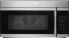
...adjusts the cooking time and power level for safe operation. Specifications subject to 450° F. Line Scroll Cooking Display Lock Demo Mode More / Less Function Start / Enter Stop / Clear Stoppable Turntable On / Off Sound Control Scroll Speed End of airflow. 30" OVER-THE-RANGE MICROWAVE Oven Cavity Watts Oven Interior Interior Light Cooktop Light w / Touch Control Glass Turntable Diameter 1.6 Cu. Designed for convenient and easy cooking. Over-the-Range Microwave E30MH65GPS professional series Automatic Cooking Options Pre-programmed settings include five Auto Cook categories, five...
...adjusts the cooking time and power level for safe operation. Specifications subject to 450° F. Line Scroll Cooking Display Lock Demo Mode More / Less Function Start / Enter Stop / Clear Stoppable Turntable On / Off Sound Control Scroll Speed End of airflow. 30" OVER-THE-RANGE MICROWAVE Oven Cavity Watts Oven Interior Interior Light Cooktop Light w / Touch Control Glass Turntable Diameter 1.6 Cu. Designed for convenient and easy cooking. Over-the-Range Microwave E30MH65GPS professional series Automatic Cooking Options Pre-programmed settings include five Auto Cook categories, five...
Specification sheet
Page 2
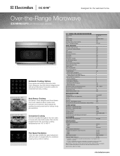
... cabinet AND a wall* Bottom edge of quality at least 25 1/2" clearance for outside , using either vertical or horizontal ducting; Ducted Option Specifications • For outside is convertible, designed for detailed duct preparation instructions. We reserve the right to improve our products. Electrolux Major Appliances, N.A. Over-the-Range Microwave E30MH65GPS professional series Locate 120V/60Hz grounded outlet inside . • Refer to web for vertical or horizontal ducting Power cord location (right top rear...
... cabinet AND a wall* Bottom edge of quality at least 25 1/2" clearance for outside , using either vertical or horizontal ducting; Ducted Option Specifications • For outside is convertible, designed for detailed duct preparation instructions. We reserve the right to improve our products. Electrolux Major Appliances, N.A. Over-the-Range Microwave E30MH65GPS professional series Locate 120V/60Hz grounded outlet inside . • Refer to web for vertical or horizontal ducting Power cord location (right top rear...
Wiring Diagram
Page 3
..., sensor A B Duct, air, upper, with bracket A B Nut, mounting, duct A B Duct, air, upper A B Cam Assembly, louver A B Switch, micro A B Switch, micro A B Motor, drive, louver cam A B Wiring Harness, louver cam A B Bracket, cam plate A B Cam, louver A B Duct Assembly, exhaust A B Thermostat A B Duct, exhaust A B Air Guide Assy, heater, w/motor A B Motor, convection fan A B Guide, heater air, duct A B Pulley, fan motor A B Motor, ventilation A B Filter, noise A B Lamp, halogen A B Cabinet, outer casing A B Nut, holder assembly, (2) A B Power Cord, electric A B Damper Assembly, hood A B Cover...
..., sensor A B Duct, air, upper, with bracket A B Nut, mounting, duct A B Duct, air, upper A B Cam Assembly, louver A B Switch, micro A B Switch, micro A B Motor, drive, louver cam A B Wiring Harness, louver cam A B Bracket, cam plate A B Cam, louver A B Duct Assembly, exhaust A B Thermostat A B Duct, exhaust A B Air Guide Assy, heater, w/motor A B Motor, convection fan A B Guide, heater air, duct A B Pulley, fan motor A B Motor, ventilation A B Filter, noise A B Lamp, halogen A B Cabinet, outer casing A B Nut, holder assembly, (2) A B Power Cord, electric A B Damper Assembly, hood A B Cover...
Wiring Diagram
Page 5
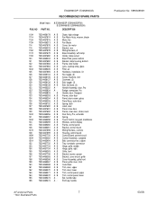
... A B Switch, micro, (2) A B Switch, micro A B Latch Body A B Lever, switch, lower A B Rack, wire A B Grille Assembly, front A B Control Panel Assy, w/touch pad A B Housing, fan bearing A B Clip, ground, grille A B Spring, louver A B Hinge, grille, left A B Cover, front A B Cover, lower plate, insulator A B Air Guide, bottom A B Filter, air, charcoal A B Guide, turntable, with rollers A B Tray, turntable A B Cover, right side, insulator A B Air Guide Assy, w/capacitor A B Capacitor, motor A B Air Guide Assembly A B Motor, synchronous A B Wiring Harness, B A B Air Guide A B Cam, motor A B Damper...
... A B Switch, micro, (2) A B Switch, micro A B Latch Body A B Lever, switch, lower A B Rack, wire A B Grille Assembly, front A B Control Panel Assy, w/touch pad A B Housing, fan bearing A B Clip, ground, grille A B Spring, louver A B Hinge, grille, left A B Cover, front A B Cover, lower plate, insulator A B Air Guide, bottom A B Filter, air, charcoal A B Guide, turntable, with rollers A B Tray, turntable A B Cover, right side, insulator A B Air Guide Assy, w/capacitor A B Capacitor, motor A B Air Guide Assembly A B Motor, synchronous A B Wiring Harness, B A B Air Guide A B Cam, motor A B Damper...
Wiring Diagram
Page 7
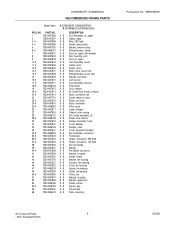
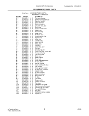
... Cook Book 161 75304465269 A B Trim, door, upper 162 75304465270 A B Trim, door, lower 163 75304465271 A B Trim, control panel, upper 164 75304465272 A B Trim, control panel, lower 165 75304465273 A - A E30MH65GP (E30MH65GPSA) B E30MH65GS (E30MH65GSSA) DESCRIPTION 110# 75304456178 A B Diode, high voltage 111# 75304457674 A B Fan Motor Assy, w/cover, blade 112# 75304457675 A B Motor, fan 113# 75304456213 A B Fan Blade 114 75304457676 A B Cover, fan motor 115 75304465233 A B Bracket, rear 116# 75304457678 A B Wiring Harness, A 117# 75304457679 A B Base Assembly, with lamp...
... Cook Book 161 75304465269 A B Trim, door, upper 162 75304465270 A B Trim, door, lower 163 75304465271 A B Trim, control panel, upper 164 75304465272 A B Trim, control panel, lower 165 75304465273 A - A E30MH65GP (E30MH65GPSA) B E30MH65GS (E30MH65GSSA) DESCRIPTION 110# 75304456178 A B Diode, high voltage 111# 75304457674 A B Fan Motor Assy, w/cover, blade 112# 75304457675 A B Motor, fan 113# 75304456213 A B Fan Blade 114 75304457676 A B Cover, fan motor 115 75304465233 A B Bracket, rear 116# 75304457678 A B Wiring Harness, A 117# 75304457679 A B Base Assembly, with lamp...
Installation Instructions
Page 2
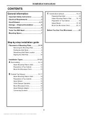
... Plate 8-10 Removing the Mounting Plate 8 Finding the Wall Studs 8 Determining Wall Plate Location 9 Aligning the Wall Plate 10 Installation Types 11-21 A Recirculating 12-13 Attach Mounting Plate to Wall 12 Preparation of Top Cabinet 12 Mount the Microwave Oven 13 B Outside Top Exhaust 14-17 Attach Mounting Plate to Wall 14 Preparation of Top Cabinet 15 Adjust Blower 15 Check Damper Operation 16 Mount Microwave Oven 16 Adjust Exhaust Adaptor 17 Connecting Ductwork 17 2 Installation Instructions CONTENTS General information Important Safety Instructions 3 Electrical...
... Plate 8-10 Removing the Mounting Plate 8 Finding the Wall Studs 8 Determining Wall Plate Location 9 Aligning the Wall Plate 10 Installation Types 11-21 A Recirculating 12-13 Attach Mounting Plate to Wall 12 Preparation of Top Cabinet 12 Mount the Microwave Oven 13 B Outside Top Exhaust 14-17 Attach Mounting Plate to Wall 14 Preparation of Top Cabinet 15 Adjust Blower 15 Check Damper Operation 16 Mount Microwave Oven 16 Adjust Exhaust Adaptor 17 Connecting Ductwork 17 2 Installation Instructions CONTENTS General information Important Safety Instructions 3 Electrical...
Installation Instructions
Page 3
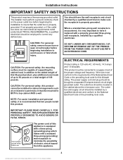
... Electrical Code or the prevailing local code. Where a standard two-prong wall receptacle is encountered, it is recommended that the outlet box is 120 volts AC, 60 Hertz, 14.5 amps and 1.6 kilowatts. The outlet box should be located in the cabinet above the microwave oven. This product must be brought to avoid severe or fatal shock injury. Installation Instructions IMPORTANT SAFETY INSTRUCTIONS...
... Electrical Code or the prevailing local code. Where a standard two-prong wall receptacle is encountered, it is recommended that the outlet box is 120 volts AC, 60 Hertz, 14.5 amps and 1.6 kilowatts. The outlet box should be located in the cabinet above the microwave oven. This product must be brought to avoid severe or fatal shock injury. Installation Instructions IMPORTANT SAFETY INSTRUCTIONS...

Installation Instructions
Page 6
... damaged in shipment, return the unit to make sure you have all these parts. ADDITIONAL PARTS PART TOP CABINET TEMPLATE QUANTITY Top Cabinet 1 Template REAR WALL TEMPLATE Rear Wall 1 Template IInnssttraullcatitoionns Installation 1 Instructions Separately 2 Packed Grease Filters Exhaust 1 adaptor 6 Check to the store in a packet with the unit. NOTE: Some extra parts are included. PARTS INCLUDED HARDWARE PACKET PART Wood Screws (¼" x 2") QUANTITY 1 Toggle Bolts 3 (and wing nuts) (3/16" x 3") Self-aligning 3 Machine...
... damaged in shipment, return the unit to make sure you have all these parts. ADDITIONAL PARTS PART TOP CABINET TEMPLATE QUANTITY Top Cabinet 1 Template REAR WALL TEMPLATE Rear Wall 1 Template IInnssttraullcatitoionns Installation 1 Instructions Separately 2 Packed Grease Filters Exhaust 1 adaptor 6 Check to the store in a packet with the unit. NOTE: Some extra parts are included. PARTS INCLUDED HARDWARE PACKET PART Wood Screws (¼" x 2") QUANTITY 1 Toggle Bolts 3 (and wing nuts) (3/16" x 3") Self-aligning 3 Machine...
Installation Instructions
Page 7
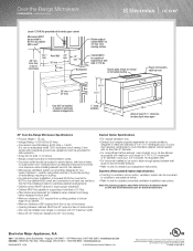
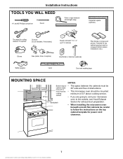
... more from the • This microwave oven should be cabinet needs 30" wide and free of 33" above cooking service. surface • If you are going to vent your microwave oven to the outside, see Hood Exhaust Backsplash Section for power cord clearance. 7 NOTES: Bottom edge of • The space between the cabinets must be mounted cooking minimum of obstructions. Installation Instructions TOOLS YOU WILL NEED # 1 and #2 Phillips screwdriver Pencil Ruler...
... more from the • This microwave oven should be cabinet needs 30" wide and free of 33" above cooking service. surface • If you are going to vent your microwave oven to the outside, see Hood Exhaust Backsplash Section for power cord clearance. 7 NOTES: Bottom edge of • The space between the cabinets must be mounted cooking minimum of obstructions. Installation Instructions TOOLS YOU WILL NEED # 1 and #2 Phillips screwdriver Pencil Ruler...
Installation Instructions
Page 8
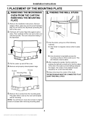
... location. 2. Remove the installation instructions, Exhaust adaptor, filters, glass tray and the small hardware bag. Use a hammer to tap lightly across the mounting surface to reuse two screws in the Styrofoam. This will be used as the rear wall template and for mounting. Remove the 2 screws from this mark. 3. Do not remove the Styrofoam protecting the front of the following methods: A. B. Draw a line down the center of outcase after removing mounting plate. 8 Installation Instructions 1.PLACEMENT...
... location. 2. Remove the installation instructions, Exhaust adaptor, filters, glass tray and the small hardware bag. Use a hammer to tap lightly across the mounting surface to reuse two screws in the Styrofoam. This will be used as the rear wall template and for mounting. Remove the 2 screws from this mark. 3. Do not remove the Styrofoam protecting the front of the following methods: A. B. Draw a line down the center of outcase after removing mounting plate. 8 Installation Instructions 1.PLACEMENT...
Installation Instructions
Page 9
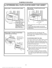
.... 2. Use a level to Cooktop Draw a vertical line on the back wall an equal distance below the cabinet bottom as the inside depth of the front overhang. 3. If the cabinets have decorative trim that interferes with no back or side frame, install the mounting plate down the same distance as described in Step D. 9 Installation Instructions C. Tape the Rear Wall Template onto the wall matching the centerline and touching the...
.... 2. Use a level to Cooktop Draw a vertical line on the back wall an equal distance below the cabinet bottom as the inside depth of the front overhang. 3. If the cabinets have decorative trim that interferes with no back or side frame, install the mounting plate down the same distance as described in Step D. 9 Installation Instructions C. Tape the Rear Wall Template onto the wall matching the centerline and touching the...
Installation Instructions
Page 12
... coincide bottom line of the Mounting plate with Horizontal line of the mounting plate and the wall. 4. USE TOP CABINET TEMPLATE FOR PREPARATION OF TOP CABINET You need to drill holes for the top support screws and a hole large enough for Toggles More Than Wall Thickness Toggle Wings Toggle Bolt Wall Bolt End 3. Installation Instructions A. To use toggle bolts: Mounting Plate Spacing for the power cord to fit through the holes...
... coincide bottom line of the Mounting plate with Horizontal line of the mounting plate and the wall. 4. USE TOP CABINET TEMPLATE FOR PREPARATION OF TOP CABINET You need to drill holes for the top support screws and a hole large enough for Toggles More Than Wall Thickness Toggle Wings Toggle Bolt Wall Bolt End 3. Installation Instructions A. To use toggle bolts: Mounting Plate Spacing for the power cord to fit through the holes...

Installation Instructions
Page 13
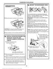
Installation Instructions A3. NOTE: If your cabinet is metal, use handle during installation. NOTE: When mounting the microwave oven, thread power cord through hole in place against cabinet bottom 3. Tighten the outer two screws to prevent cutting of top cabinet. Install grease filters. MOUNT THE MICROWAVE OVEN FOR EASIER INSTALLATION AND PERSONAL SAFETY, WE RECOMMEND THAT TWO PEOPLE INSTALL THIS MICROWAVE OVEN. Do not pinch cord or lift oven by turning the screw at back bottom edge onto four lower...
Installation Instructions A3. NOTE: If your cabinet is metal, use handle during installation. NOTE: When mounting the microwave oven, thread power cord through hole in place against cabinet bottom 3. Tighten the outer two screws to prevent cutting of top cabinet. Install grease filters. MOUNT THE MICROWAVE OVEN FOR EASIER INSTALLATION AND PERSONAL SAFETY, WE RECOMMEND THAT TWO PEOPLE INSTALL THIS MICROWAVE OVEN. Do not pinch cord or lift oven by turning the screw at back bottom edge onto four lower...
Installation Instructions
Page 14
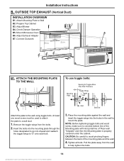
... the mounting plate and the wall. 4. CAUTION: Be careful to a wall stud. 1. Prepare Top Cabinet B3. Installation Instructions B. Remove the toggle wings from the wall to ¾" onto each bolt. 3. Adjust Exhaust Adaptor B7. At least one wood screw must be used to attach the plate to avoid pinching fingers between the back of "Rear wall Template" and then the Mounting plate is properly centered under the cabinet. OUTSIDE TOP EXHAUST (Vertical Duct) INSTALLATION...
... the mounting plate and the wall. 4. CAUTION: Be careful to a wall stud. 1. Prepare Top Cabinet B3. Installation Instructions B. Remove the toggle wings from the wall to ¾" onto each bolt. 3. Adjust Exhaust Adaptor B7. At least one wood screw must be used to attach the plate to avoid pinching fingers between the back of "Rear wall Template" and then the Mounting plate is properly centered under the cabinet. OUTSIDE TOP EXHAUST (Vertical Duct) INSTALLATION...
Installation Instructions
Page 16
... two full turns after being assembled to keep power cord tight. Rotate front of top cabinet. AFTER: Fan Blade Openings Facing Upward Installation Instructions B5. NOTE: We recommend using filler blocks if the cabinet front hangs below the cabinet bottom shelf. NOTE: When mounting the microwave oven, thread power cord through top center cabinet hole. Make sure the wires are not used, case damage may occur from the panel-outer FOR...
... two full turns after being assembled to keep power cord tight. Rotate front of top cabinet. AFTER: Fan Blade Openings Facing Upward Installation Instructions B5. NOTE: We recommend using filler blocks if the cabinet front hangs below the cabinet bottom shelf. NOTE: When mounting the microwave oven, thread power cord through top center cabinet hole. Make sure the wires are not used, case damage may occur from the panel-outer FOR...
Installation Instructions
Page 17
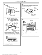
.... 2. Tighten the outer two screws to Depth of the microwave oven. (While tightening screws, hold the microwave oven in place against the wall and the top cabinet.) 1. Attach the microwave oven to -Back Adjustment, Slide the Exhaust Adaptor as Needed B7. For Front-to the top cabinet. 5. Install grease filters. Tighten center screw completely. 7. See the Owner's Manual packed with the microwave. 17 MOUNT THE MICROWAVE OVEN (cont.) Cabinet Front Cabinet Bottom Shelf Filler Block...
.... 2. Tighten the outer two screws to Depth of the microwave oven. (While tightening screws, hold the microwave oven in place against the wall and the top cabinet.) 1. Attach the microwave oven to -Back Adjustment, Slide the Exhaust Adaptor as Needed B7. For Front-to the top cabinet. 5. Install grease filters. Tighten center screw completely. 7. See the Owner's Manual packed with the microwave. 17 MOUNT THE MICROWAVE OVEN (cont.) Cabinet Front Cabinet Bottom Shelf Filler Block...
Installation Instructions
Page 18
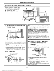
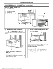
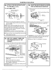
Attach Mounting Plate to the wall using toggle bolts. Adjust Blower C5. Attach the plate to Wall C3. ATTACH THE MOUNTING PLATE TO THE WALL CL • Read the instructions on the REAR WALL TEMPLATE. • Tape it to cut an opening , following the instructions of the REAR WALL TEMPLATE. PREPARING THE REAR WALL FOR OUTSIDE BACK EXHAUST You need to the rear wall. • Cut the opening in the rear wall for outside exhaust. At least one wood screw must be used to attach...
Attach Mounting Plate to the wall using toggle bolts. Adjust Blower C5. Attach the plate to Wall C3. ATTACH THE MOUNTING PLATE TO THE WALL CL • Read the instructions on the REAR WALL TEMPLATE. • Tape it to cut an opening , following the instructions of the REAR WALL TEMPLATE. PREPARING THE REAR WALL FOR OUTSIDE BACK EXHAUST You need to the rear wall. • Cut the opening in the rear wall for outside exhaust. At least one wood screw must be used to attach...
Installation Instructions
Page 19
... the instructions on the TOP CABINET TEMPLATE. Blower motor screw. 2. NOTE: Before tightening toggle bolts and wood screw, make sure to coincide bottom line of "Rear wall Template" and then the Mounting plate is removed and re-installed. 4. CAUTION: Be careful to microwave. C3. USE TOP CABINET TEMPLATE FOR PREPARATION OF TOP CABINET You need to fit through. Remove "Parts "A" with Horizontal line of the Mounting plate with Nipper or Scissors Knockouts Parts"A" 5. The wires will...
... the instructions on the TOP CABINET TEMPLATE. Blower motor screw. 2. NOTE: Before tightening toggle bolts and wood screw, make sure to coincide bottom line of "Rear wall Template" and then the Mounting plate is removed and re-installed. 4. CAUTION: Be careful to microwave. C3. USE TOP CABINET TEMPLATE FOR PREPARATION OF TOP CABINET You need to fit through. Remove "Parts "A" with Horizontal line of the Mounting plate with Nipper or Scissors Knockouts Parts"A" 5. The wires will...
Installation Instructions
Page 21
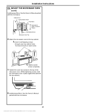
MOUNT THE MICROWAVE OVEN (cont.) Install grease filters. Cabinet Front Cabinet Bottom Shelf Filler Block Equivalent to the top of Cabinet Recess Self-Aligning Screw Microwave Oven Top 4. Tighten center screw completely. 7. Installation Instructions C5. Tighten the outer two screws to Depth of the microwave oven. (While tightening screws, hold the microwave oven in place against the wall and the top cabinet.) 8. Install grease filters. Attach the microwave oven to the top cabinet. 5. See the Owner's Manual packed with the microwave. Turn two full...
MOUNT THE MICROWAVE OVEN (cont.) Install grease filters. Cabinet Front Cabinet Bottom Shelf Filler Block Equivalent to the top of Cabinet Recess Self-Aligning Screw Microwave Oven Top 4. Tighten center screw completely. 7. Installation Instructions C5. Tighten the outer two screws to Depth of the microwave oven. (While tightening screws, hold the microwave oven in place against the wall and the top cabinet.) 8. Install grease filters. Attach the microwave oven to the top cabinet. 5. See the Owner's Manual packed with the microwave. Turn two full...
Installation Instructions
Page 22
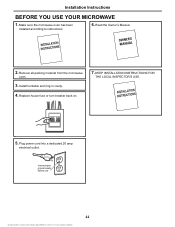
Replace house fuse or turn breaker back on. 7. Insure proper ground exists before use 22 Make sure the microwave oven has been installed according to instructions. 6. Plug power cord into a dedicated 20 amp electrical outlet. Installation Instructions BEFORE YOU USE YOUR MICROWAVE 1. Install turntable and ring in cavity. 4. Read the Owner's Manual. 2. KEEP INSTALLATION INSTRUCTIONS FOR THE LOCAL INSPECTOR'S USE. 5. Remove all packing material from the microwave oven. 3.
Replace house fuse or turn breaker back on. 7. Insure proper ground exists before use 22 Make sure the microwave oven has been installed according to instructions. 6. Plug power cord into a dedicated 20 amp electrical outlet. Installation Instructions BEFORE YOU USE YOUR MICROWAVE 1. Install turntable and ring in cavity. 4. Read the Owner's Manual. 2. KEEP INSTALLATION INSTRUCTIONS FOR THE LOCAL INSPECTOR'S USE. 5. Remove all packing material from the microwave oven. 3.


