
PDF Spec Sheet
Page 1
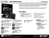
...; 2 PCI Express Graphics Expansion slots • 14 USB 2.0 ports (eight rear panel, six onboard) • 6 SATA II Ports supporting 300MB/s • 2 1394 Ports (two onboard) • 1 Gigabit Ethernet Port (10/100/100o) • 8 Channel Audio w/ SPDIF and COAX 6+1 Phase PWM w/ switching --' frequency up to eight threads of computing power, dual-channel DDR3 memory at frequencies of up to be installed for adjusting ,= 17 overclocking in O.S. An enthusiast layout allows both Socket 775 and Socket 1156 heatsinks z"/ EVGA ELEET Tuning Utility Enthusiast software for...
...; 2 PCI Express Graphics Expansion slots • 14 USB 2.0 ports (eight rear panel, six onboard) • 6 SATA II Ports supporting 300MB/s • 2 1394 Ports (two onboard) • 1 Gigabit Ethernet Port (10/100/100o) • 8 Channel Audio w/ SPDIF and COAX 6+1 Phase PWM w/ switching --' frequency up to eight threads of computing power, dual-channel DDR3 memory at frequencies of up to be installed for adjusting ,= 17 overclocking in O.S. An enthusiast layout allows both Socket 775 and Socket 1156 heatsinks z"/ EVGA ELEET Tuning Utility Enthusiast software for...
User Guide
Page 3
... P55 LE Motherboard Table of Contents User's Guide ...1 EVGA P55 LE Motherboard 1 Before You Begin...7 Parts NOT in the Kit 7 EVGA P55 LE Motherboard 8 Motherboard Specifications 8 Hardware Installation 10 Safety Instructions 10 Preparing the Motherboard 11 Installing the CPU 11 Installing the CPU Fan 12 Installing System Memory (DIMMs 13 Installing the Motherboard 13 Installing the I/O Shield 14 Securing the Motherboard into a System Case 15 Connecting Cables 15 24-pin ATX Power (PW1 16 8-pin ATX 12V Power (PW12 16 Connecting Serial ATA Cables 16 Connecting Internal Headers...
... P55 LE Motherboard Table of Contents User's Guide ...1 EVGA P55 LE Motherboard 1 Before You Begin...7 Parts NOT in the Kit 7 EVGA P55 LE Motherboard 8 Motherboard Specifications 8 Hardware Installation 10 Safety Instructions 10 Preparing the Motherboard 11 Installing the CPU 11 Installing the CPU Fan 12 Installing System Memory (DIMMs 13 Installing the Motherboard 13 Installing the I/O Shield 14 Securing the Motherboard into a System Case 15 Connecting Cables 15 24-pin ATX Power (PW1 16 8-pin ATX 12V Power (PW12 16 Connecting Serial ATA Cables 16 Connecting Internal Headers...
User Guide
Page 5
POST Codes for the EVGA P55 LE Motherboard 40 EVGA P55 LE Motherboard Allocate IRQ to PCI VGA 34 Palette Snooping 34 PCI IDE BusMaster 34 OffBoard PCI/ISA IDE Card 34 IRQ Settings ...34 Boot Configuration Features 35 Boot Device Priority 35 Hard Disk Drives 35 CD/DVD Drives 36 Power Management Features 36 ACPI Configuration 36 SLP_S4# Min. Assertion Width 36 Restore on AC Power Loss 37 Hardware Health Configure 37 H/W Health Function 37 CPU Fan Mode Setting 38 Frequency/Voltage Control Menu 38 Memory Configure 38 CPU Configuration 38 Installing Drivers and Software 39 ...
POST Codes for the EVGA P55 LE Motherboard 40 EVGA P55 LE Motherboard Allocate IRQ to PCI VGA 34 Palette Snooping 34 PCI IDE BusMaster 34 OffBoard PCI/ISA IDE Card 34 IRQ Settings ...34 Boot Configuration Features 35 Boot Device Priority 35 Hard Disk Drives 35 CD/DVD Drives 36 Power Management Features 36 ACPI Configuration 36 SLP_S4# Min. Assertion Width 36 Restore on AC Power Loss 37 Hardware Health Configure 37 H/W Health Function 37 CPU Fan Mode Setting 38 Frequency/Voltage Control Menu 38 Memory Configure 38 CPU Configuration 38 Installing Drivers and Software 39 ...
User Guide
Page 7
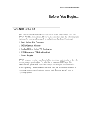
... hardware necessary to install and connect your new EVGA P55 LE Motherboard. Parts NOT in a system case, you have an operating system. EVGA P55 LE Motherboard Before You Begin... However, it does not contain the following items that must be purchased separately to make the motherboard functional. Intel Socket 1156 Processor DDR3 System Memory Socket 1156 or Socket 775 Cooling fan PCI Express or PCI Graphics Card Power Supply EVGA assumes you...
... hardware necessary to install and connect your new EVGA P55 LE Motherboard. Parts NOT in a system case, you have an operating system. EVGA P55 LE Motherboard Before You Begin... However, it does not contain the following items that must be purchased separately to make the motherboard functional. Intel Socket 1156 Processor DDR3 System Memory Socket 1156 or Socket 775 Cooling fan PCI Express or PCI Graphics Card Power Supply EVGA assumes you...
User Guide
Page 8
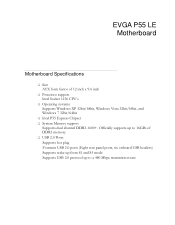
... Mbps transmission rate EVGA P55 LE Motherboard Motherboard Specifications Size ATX form factor of DDR3 memory. USB 2.0 Ports Supports hot plug Fourteen USB 2.0 ports (Eight rear panel ports, six onboard USB headers) Supports wake-up from S1 and S3 mode Supports USB 2.0 protocol up to 16GBs of 12 inch x 9.6 inch Processor support Intel Socket 1156 CPU's Operating systems: Supports Windows XP 32bit/64bit, Windows Vista 32bit/64bit, and Windows 7 32bit/64bit Intel P55 Express Chipset System Memory support Supports dual channel DDR3-1600...
... Mbps transmission rate EVGA P55 LE Motherboard Motherboard Specifications Size ATX form factor of DDR3 memory. USB 2.0 Ports Supports hot plug Fourteen USB 2.0 ports (Eight rear panel ports, six onboard USB headers) Supports wake-up from S1 and S3 mode Supports USB 2.0 protocol up to 16GBs of 12 inch x 9.6 inch Processor support Intel Socket 1156 CPU's Operating systems: Supports Windows XP 32bit/64bit, Windows Vista 32bit/64bit, and Windows 7 32bit/64bit Intel P55 Express Chipset System Memory support Supports dual channel DDR3-1600...

User Guide
Page 15
... offs located inside the chassis. 2. Align the mounting holes with a mounting hole on the motherboard. Connecting Cables This section takes you remove that the fan assembly is recommended to secure the motherboard using a minimum of nine (9) screws. This will include: Power Connections 24-pin ATX power (PW1) 8-pin ATX 12V power (PW12) Internal Headers Front panel IEEE 1394a USB Headers Audio Serial ATA II USB 2.0 Expansion slots CMOS Clear Button In most cases, it...
... offs located inside the chassis. 2. Align the mounting holes with a mounting hole on the motherboard. Connecting Cables This section takes you remove that the fan assembly is recommended to secure the motherboard using a minimum of nine (9) screws. This will include: Power Connections 24-pin ATX power (PW1) 8-pin ATX 12V power (PW12) Internal Headers Front panel IEEE 1394a USB Headers Audio Serial ATA II USB 2.0 Expansion slots CMOS Clear Button In most cases, it...

User Guide
Page 18
... the hard disk drive indicator LED cable to these two pins. Connecting Internal Headers Front Panel Header The front panel header on this motherboard is on. Pressing the power button on the front panel turns the system on and off . Be sure to match the name on , the LED is one connector used to connect the following four cables. (see Table 2 for pin definitions): PWRLED Attach the front panel power LED cable to these two pins of the case...
... the hard disk drive indicator LED cable to these two pins. Connecting Internal Headers Front Panel Header The front panel header on this motherboard is on. Pressing the power button on the front panel turns the system on and off . Be sure to match the name on , the LED is one connector used to connect the following four cables. (see Table 2 for pin definitions): PWRLED Attach the front panel power LED cable to these two pins of the case...

User Guide
Page 22
... card's metal bracket to the chassis back panel with PCI specifications. Expansion Slots PCI Slots The PCI slot supports many expansion cards such as a LAN card, USB card, SCSI card and other cards that is designed to accommodate PCIe x1 cards, such as an EVGA Killer Xeno Network Card or Sound Card. When installing a card into the PCI slot, be sure the retention clip snaps and locks the card into place. When installing a PCI Express Graphic Card, be sure that it could cause a short across the pins...
... card's metal bracket to the chassis back panel with PCI specifications. Expansion Slots PCI Slots The PCI slot supports many expansion cards such as a LAN card, USB card, SCSI card and other cards that is designed to accommodate PCIe x1 cards, such as an EVGA Killer Xeno Network Card or Sound Card. When installing a card into the PCI slot, be sure the retention clip snaps and locks the card into place. When installing a PCI Express Graphic Card, be sure that it could cause a short across the pins...
User Guide
Page 26
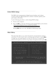
... Boot Configuration Features Power Management Features Hardware Health Configure Frequency/Voltage Control Load Optimal Defaults Discard Changes Save & Exit Setup Discard Changes and Exit Move Enter:Select +/-/:Valve F10:Save ESC:Exit F1: General Help F7:Previous Values F9: Optimized Defaults Configure Time and Date. Press the Del key when the following procedure to enter Setup. Use the arrow keys to the AMI BIOS CMOS Setup Utility. Pressing...
... Boot Configuration Features Power Management Features Hardware Health Configure Frequency/Voltage Control Load Optimal Defaults Discard Changes Save & Exit Setup Discard Changes and Exit Move Enter:Select +/-/:Valve F10:Save ESC:Exit F1: General Help F7:Previous Values F9: Optimized Defaults Configure Time and Date. Press the Del key when the following procedure to enter Setup. Use the arrow keys to the AMI BIOS CMOS Setup Utility. Pressing...
User Guide
Page 27
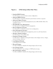
... onboard peripherals such as IDE, RAID, USB, LAN, and MAC control. PCI/PNP Resource Management Use this menu to configure resource management. Boot Configuration Features Use this menu to modify the system's boot configuration. Power Management Features Use this menu to modify power management, power on, and sleep features. Hardware Health Configure Use this menu to view system vitals. Frequency/Voltage Control Use this menu to optimize system performance and configure clocks, voltages, memory timings, and more. Load Optimal Defaults Load...
... onboard peripherals such as IDE, RAID, USB, LAN, and MAC control. PCI/PNP Resource Management Use this menu to configure resource management. Boot Configuration Features Use this menu to modify the system's boot configuration. Power Management Features Use this menu to modify power management, power on, and sleep features. Hardware Health Configure Use this menu to view system vitals. Frequency/Voltage Control Use this menu to optimize system performance and configure clocks, voltages, memory timings, and more. Load Optimal Defaults Load...

User Guide
Page 30
... to enable RAID or switch between IDE and AHCI mode. Advanced BIOS Features IDE Configuration Use this option to change advanced AHCI settings, such as Bootup Num-Lock status, Quiet Boot and other advanced features. Boot Settings Configuration Use this to configure your storage drivers and to malfunction. IDE Configuration [Press Enter] Boot Settings Configuration[Press Enter] AHCI Configuration [Press Enter] USB Configuration [Press Enter] Help Item Main Level Select Removable Boot Device Priority Move Enter:Select +/-/:Value...
... to enable RAID or switch between IDE and AHCI mode. Advanced BIOS Features IDE Configuration Use this option to change advanced AHCI settings, such as Bootup Num-Lock status, Quiet Boot and other advanced features. Boot Settings Configuration Use this to configure your storage drivers and to malfunction. IDE Configuration [Press Enter] Boot Settings Configuration[Press Enter] AHCI Configuration [Press Enter] USB Configuration [Press Enter] Help Item Main Level Select Removable Boot Device Priority Move Enter:Select +/-/:Value...
User Guide
Page 31
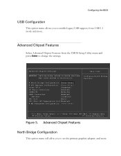
...F7:Optimized Defaults Figure 5. Advanced Chipset Features North Bridge Configuration This option menu will allow you to enable Legacy USB support, force USB 1.1 mode and more . Advanced Chipset Features Select Advanced Chipset Features from the CMOS Setup Utility menu and press Enter to malfunction. North Bridge Configuration [Press Enter] PCI Express Configuration [Press Enter] Intel VT-d [Disabled] HD Audio Controller [Enabled] IEEE1394 [Enabled] LAN1 Controller [Enabled] LAN Boot [Disabled] PE1 Slot [Auto] P80 Show CPU Temperature Slot[Enabled] ...
...F7:Optimized Defaults Figure 5. Advanced Chipset Features North Bridge Configuration This option menu will allow you to enable Legacy USB support, force USB 1.1 mode and more . Advanced Chipset Features Select Advanced Chipset Features from the CMOS Setup Utility menu and press Enter to malfunction. North Bridge Configuration [Press Enter] PCI Express Configuration [Press Enter] Intel VT-d [Disabled] HD Audio Controller [Enabled] IEEE1394 [Enabled] LAN1 Controller [Enabled] LAN Boot [Disabled] PE1 Slot [Auto] P80 Show CPU Temperature Slot[Enabled] ...

User Guide
Page 32
... enable, or disable, Virtualization Technology for standard system setups. The Advanced Chipset Features menu also allows you to enable/disable some onboard devices, they are using an external Network Controller, such as an EVGA Killer Xeno card. PE1 Slot This function allows you to enable or disable the PE1 Slot. It is recommended to leave this enabled, unless you are as Payload size. ME Subsystem Configuration Select this option to adjust these settings. PCI Express Configuration This option menu...
... enable, or disable, Virtualization Technology for standard system setups. The Advanced Chipset Features menu also allows you to enable/disable some onboard devices, they are using an external Network Controller, such as an EVGA Killer Xeno card. PE1 Slot This function allows you to enable or disable the PE1 Slot. It is recommended to leave this enabled, unless you are as Payload size. ME Subsystem Configuration Select this option to adjust these settings. PCI Express Configuration This option menu...

User Guide
Page 33
... Values F7:Optimized Defaults Figure 6. Advanced PCI/PnP Settings WARNING: Setting wrong values in units of [No] is default. A setting of PCI clocks. Plug & Play O/S This function sets whether the O/S or BIOS configures Plug and Play devices. Help Item Clear NVRAM during System Boot. Clear NVRAM Plug & Play O/S PCI Latency Timer Allocate IRQ to malfunction. PCI/PNP Resource Management Select PCI/PNP Resource Management from the CMOS Setup Utility menu and press Enter to display the advanced...
... Values F7:Optimized Defaults Figure 6. Advanced PCI/PnP Settings WARNING: Setting wrong values in units of [No] is default. A setting of PCI clocks. Plug & Play O/S This function sets whether the O/S or BIOS configures Plug and Play devices. Help Item Clear NVRAM during System Boot. Clear NVRAM Plug & Play O/S PCI Latency Timer Allocate IRQ to malfunction. PCI/PNP Resource Management Select PCI/PNP Resource Management from the CMOS Setup Utility menu and press Enter to display the advanced...

User Guide
Page 35
...:Fail-Safe Defaults F7:Optimized Defaults Figure 7. Boot Configuration Features Boot Device Priority This option menu will allow specification of the Hard Disk boot priority sequence. Hard Disk Drives This option menu allows you specification of the boot device priority sequence. Boot Configuration Features Select Boot Configuration Features from the CMOS Setup Utility menu and press Enter to display the settings. Boot Device Priority Hard Disk Drives CD/DVD Drives [Press Enter] [Press Enter] [Press Enter] Help Item Specifies the Boot Device Priority...
...:Fail-Safe Defaults F7:Optimized Defaults Figure 7. Boot Configuration Features Boot Device Priority This option menu will allow specification of the Hard Disk boot priority sequence. Hard Disk Drives This option menu allows you specification of the boot device priority sequence. Boot Configuration Features Select Boot Configuration Features from the CMOS Setup Utility menu and press Enter to display the settings. Boot Device Priority Hard Disk Drives CD/DVD Drives [Press Enter] [Press Enter] [Press Enter] Help Item Specifies the Boot Device Priority...

User Guide
Page 36
... Values F6:Fail-Safe Defaults F7:Optimized Defaults Figure 8. CD/DVD Drives This option menu allows you specification of the SLP assertion width. Assertion Width This function allows adjustment of the CD/DVD boot priority sequence. Power Management Features ACPI Configuration This menu will allow adjustment of Advanced ACPI configurations. Assertion Width [4 to display the settings. Power Management Features Select Power Management Features from the CMOS Setup Utility menu and press Enter to 5 seconds] ...
... Values F6:Fail-Safe Defaults F7:Optimized Defaults Figure 8. CD/DVD Drives This option menu allows you specification of the SLP assertion width. Assertion Width This function allows adjustment of the CD/DVD boot priority sequence. Power Management Features ACPI Configuration This menu will allow adjustment of Advanced ACPI configurations. Assertion Width [4 to display the settings. Power Management Features Select Power Management Features from the CMOS Setup Utility menu and press Enter to 5 seconds] ...

User Guide
Page 37
... F5:Previous Values F6:Fail-Safe Defaults F7:Optimized Defaults Figure 9. Hardware Health Configure H/W Health Function This will enable or disable Hardware Health Monitoring. Configuring the BIOS Restore on AC Power Loss This menu allows adjustment of the AC Power Loss parameters. Hardware Health Configure H/W Health Function [Enabled] CPU Temperature Sensor VREG Temperature Sensor System Temperature Sensor :34C/93F :48C/118F :34C/93F CPU Fan Speed Power Fan Speed Chassis Fan Speed :3264 RPM :1337 RPM :3864...
... F5:Previous Values F6:Fail-Safe Defaults F7:Optimized Defaults Figure 9. Hardware Health Configure H/W Health Function This will enable or disable Hardware Health Monitoring. Configuring the BIOS Restore on AC Power Loss This menu allows adjustment of the AC Power Loss parameters. Hardware Health Configure H/W Health Function [Enabled] CPU Temperature Sensor VREG Temperature Sensor System Temperature Sensor :34C/93F :48C/118F :34C/93F CPU Fan Speed Power Fan Speed Chassis Fan Speed :3264 RPM :1337 RPM :3864...

User Guide
Page 38
Frequency/Voltage Control Menu Select Frequency/Voltage Control from the CMOS Setup Utility menu and press Enter to display the settings. AwardBIOS CMOS Setup Utility Frequency/Voltage Control Memory Configure CPU Configuration [Press Enter] [Press Enter] CPU Multiplier Setting CPU Frequency Setting PCIE Frequency Setting [20] [133] [100] EVGA VDroop Control [With VDroop] Current CPU VCore : 1.33700V CPU VCore [Auto] Current Dimm Voltage : 1.50V DIMM Voltage [Auto] Current VTT : 1.050V VTT [Auto] Current PCH Voltage : 1.050V PCH [Auto] Current CPU PLL : ...
Frequency/Voltage Control Menu Select Frequency/Voltage Control from the CMOS Setup Utility menu and press Enter to display the settings. AwardBIOS CMOS Setup Utility Frequency/Voltage Control Memory Configure CPU Configuration [Press Enter] [Press Enter] CPU Multiplier Setting CPU Frequency Setting PCIE Frequency Setting [20] [133] [100] EVGA VDroop Control [With VDroop] Current CPU VCore : 1.33700V CPU VCore [Auto] Current Dimm Voltage : 1.50V DIMM Voltage [Auto] Current VTT : 1.050V VTT [Auto] Current PCH Voltage : 1.050V PCH [Auto] Current CPU PLL : ...
User Guide
Page 39
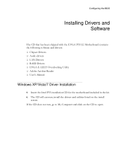
... been shipped with the EVGA P55 LE Motherboard contains the following software and drivers: Chipset Drivers Audio drivers LAN Drivers RAID Drivers EVGA E-LEET Overclocking Utility Adobe Acrobat Reader User's Manual Windows XP/Vista/7 Driver Installation 5. Insert the Intel P55 installation CD for the motherboard included in the kit. 6. If the CD does not run, go to open. The CD will autorun, install the drivers and utilities listed on the CD to...
... been shipped with the EVGA P55 LE Motherboard contains the following software and drivers: Chipset Drivers Audio drivers LAN Drivers RAID Drivers EVGA E-LEET Overclocking Utility Adobe Acrobat Reader User's Manual Windows XP/Vista/7 Driver Installation 5. Insert the Intel P55 installation CD for the motherboard included in the kit. 6. If the CD does not run, go to open. The CD will autorun, install the drivers and utilities listed on the CD to...

User Guide
Page 40
... of CPU Secondary initialization of CPU Set up boot strap processor information Set up boot strap processor for POST Enumerate and set up application processors Re-enable cache for the EVGA P55 LE Motherboard during system boot up. POST Codes for the EVGA P55 LE Motherboard This section provides the AMI POST Codes (Table 6) for boot strap processor Early CPU initialization exit Initialize keyboard controller Detect Mouse Detect Keyboard Test input devices Early POST initialization of chipset registers This Debug LED will also display current CPU temperatures after...
... of CPU Secondary initialization of CPU Set up boot strap processor information Set up boot strap processor for POST Enumerate and set up application processors Re-enable cache for the EVGA P55 LE Motherboard during system boot up. POST Codes for the EVGA P55 LE Motherboard This section provides the AMI POST Codes (Table 6) for boot strap processor Early CPU initialization exit Initialize keyboard controller Detect Mouse Detect Keyboard Test input devices Early POST initialization of chipset registers This Debug LED will also display current CPU temperatures after...


