User Manual
Page 2
User's Guide EVGA nForce 730i Motherboard
User's Guide EVGA nForce 730i Motherboard

User Manual
Page 4
... Kit ix EVGA nForce 730i Motherboard 1 Motherboard Specifications 1 Unpacking and Parts Descriptions 4 Unpacking ...4 Equipment ...4 EVGA nForce 730i Motherboard 5 Hardware Installation 8 Safety Instructions 8 Preparing the Motherboard 9 Installing the CPU 9 Installing the CPU Fan 10 Installing System Memory (DIMMs 10 Installing the Motherboard 11 Installing the I/O Shield 12 Securing the Motherboard into a System Case 12 Connecting Cables and Setting Switches 12 24-pin ATX Power...
... Kit ix EVGA nForce 730i Motherboard 1 Motherboard Specifications 1 Unpacking and Parts Descriptions 4 Unpacking ...4 Equipment ...4 EVGA nForce 730i Motherboard 5 Hardware Installation 8 Safety Instructions 8 Preparing the Motherboard 9 Installing the CPU 9 Installing the CPU Fan 10 Installing System Memory (DIMMs 10 Installing the Motherboard 11 Installing the I/O Shield 12 Securing the Motherboard into a System Case 12 Connecting Cables and Setting Switches 12 24-pin ATX Power...
User Manual
Page 6
EVGA nForce 730i Motherboard Memory ...34 Advanced BIOS Features Menu 35 Removable Device Priority 36 Hard Disk Boot Priority 36 CD-ROM Boot Priority 36 First/Second/Third Boot ... dev to Gen2 41 System BIOS Cacheable 42 Integrated Peripherals Menu 43 Storage Config 44 Onboard Devices 45 Legacy Devices 45 USB Device Setting 46 EVGA v
EVGA nForce 730i Motherboard Memory ...34 Advanced BIOS Features Menu 35 Removable Device Priority 36 Hard Disk Boot Priority 36 CD-ROM Boot Priority 36 First/Second/Third Boot ... dev to Gen2 41 System BIOS Cacheable 42 Integrated Peripherals Menu 43 Storage Config 44 Onboard Devices 45 Legacy Devices 45 USB Device Setting 46 EVGA v

User Manual
Page 8
EVGA nForce 730i Motherboard Appendix A POST Codes for the EVGA nForce 730i Motherboard 68 EVGA vii
EVGA nForce 730i Motherboard Appendix A POST Codes for the EVGA nForce 730i Motherboard 68 EVGA vii

User Manual
Page 9
Figure 6. Figure 2. Figure 5. List of Figures PW1 Motherboard Connector 14 BIOS CMOS Setup Utility Main Menu 28 Standard CMOS Features Menu 30 Advanced BIOS Features Menu 35 Advanced Chipset Features 39 Integrated Peripherals Menu 43 Power Management Setup Menu 47 PnP/PCI Configuration Menu 50 PC Health Status Menu 53 Frequency/Voltage Control Menu 55 System Clocks Menu 56 FSB & Memory Config Menu 57 System Voltages Menu 61 EVGA viii Figure 5. Figure 7. Figure 9. Figure 8. Figure 6. Figure 4. Figure 2. Figure 3. Figure 3. Figure 4.
Figure 6. Figure 2. Figure 5. List of Figures PW1 Motherboard Connector 14 BIOS CMOS Setup Utility Main Menu 28 Standard CMOS Features Menu 30 Advanced BIOS Features Menu 35 Advanced Chipset Features 39 Integrated Peripherals Menu 43 Power Management Setup Menu 47 PnP/PCI Configuration Menu 50 PC Health Status Menu 53 Frequency/Voltage Control Menu 55 System Clocks Menu 56 FSB & Memory Config Menu 57 System Voltages Menu 61 EVGA viii Figure 5. Figure 7. Figure 9. Figure 8. Figure 6. Figure 4. Figure 2. Figure 3. Figure 3. Figure 4.

User Manual
Page 10
...not need to reinstall an operating system even though the current drives have purchased all necessary parts needed to install the motherboard into a system case. EVGA ix Intentions of the Kit This kit provides you will use most of the cables. If however, you are building...137; System Memory ‰ Cooling fan for the Microprocessor ‰ Graphics Card ‰ Power Supply EVGA assumes you will need many of the cables provided in the kit. EVGA nForce 730i Motherboard Before You Begin... However, it does not contain the following items that must be purchased separately to ...
...not need to reinstall an operating system even though the current drives have purchased all necessary parts needed to install the motherboard into a system case. EVGA ix Intentions of the Kit This kit provides you will use most of the cables. If however, you are building...137; System Memory ‰ Cooling fan for the Microprocessor ‰ Graphics Card ‰ Power Supply EVGA assumes you will need many of the cables provided in the kit. EVGA nForce 730i Motherboard Before You Begin... However, it does not contain the following items that must be purchased separately to ...

User Manual
Page 12
Motherboard Specifications ‰ Size ATX form factor of 12 inch x 9.5 inch ‰ Microprocessor support ¾ Intel Core 2 Extreme, Intel Core 2 Quad, Intel Core 2 Duo, Pentium EE, Pentium D, Pentium ¾ Intel ... bus (FSB) interface with Hyper-Threading Technology support, running at up to 2560x1600 ¾ GeForce Boost Technology which increases the performance of a discrete GeForce GPUs EVGA 1 EVGA nForce 730i Motherboard Thank you for analog display resolutions up to 1333 MHz ‰ Operating systems: Supports Windows XP 32bit/64bit and Windows Vista 32bit/64bit ‰ Contains...
Motherboard Specifications ‰ Size ATX form factor of 12 inch x 9.5 inch ‰ Microprocessor support ¾ Intel Core 2 Extreme, Intel Core 2 Quad, Intel Core 2 Duo, Pentium EE, Pentium D, Pentium ¾ Intel ... bus (FSB) interface with Hyper-Threading Technology support, running at up to 2560x1600 ¾ GeForce Boost Technology which increases the performance of a discrete GeForce GPUs EVGA 1 EVGA nForce 730i Motherboard Thank you for analog display resolutions up to 1333 MHz ‰ Operating systems: Supports Windows XP 32bit/64bit and Windows Vista 32bit/64bit ‰ Contains...

User Manual
Page 14
off) ‰ Expansion Slots ¾ Three PCI slots ¾ Two PCI Express x1 slot ¾ One PCI Express x16 Graphics slots with PCI Express 2.0 EVGA 3 depends on suspend), S3 (suspend to RAM), S4 (Suspend to disk - EVGA nForce 730i Motherboard ‰ Green Function ¾ Supports ACPI (Advanced Configuration and Power Interface) ¾ Supports S0 (normal), S1 (power on OS), and S5 (soft -
off) ‰ Expansion Slots ¾ Three PCI slots ¾ Two PCI Express x1 slot ¾ One PCI Express x16 Graphics slots with PCI Express 2.0 EVGA 3 depends on suspend), S3 (suspend to RAM), S4 (Suspend to disk - EVGA nForce 730i Motherboard ‰ Green Function ¾ Supports ACPI (Advanced Configuration and Power Interface) ¾ Supports S0 (normal), S1 (power on OS), and S5 (soft -

User Manual
Page 15
... internal components from dust, foreign objects, and aids in this kit are replacing a motherboard, you may not need many of the motherboard. 1 - Equipment The following equipment is Hybrid SLIready. 1 - I/O Shield Installs in the motherboard box. The EVGA nForce 730i Motherboard This PCI Express motherboard contains the NVIDIA GeForce 9300 Chipset and is included in the system case to...
... internal components from dust, foreign objects, and aids in this kit are replacing a motherboard, you may not need many of the motherboard. 1 - Equipment The following equipment is Hybrid SLIready. 1 - I/O Shield Installs in the motherboard box. The EVGA nForce 730i Motherboard This PCI Express motherboard contains the NVIDIA GeForce 9300 Chipset and is included in the system case to...
User Manual
Page 16
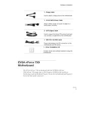
... software needed to a SATA power connector. 2 - EVGA 5 Floppy Cable Used to attach a floppy drive to the motherboard. 1 - 2-Port SATA Power Cable Allows a Molex power connector to adapt to setup the motherboard. EVGA nForce 730i Motherboard The EVGA nForce 730i motherboard with the NVIDIA GeForce 9300/nForce 730i single chip is a PCI Express, NVIDIA GeForce Boost Technology ready motherboard. SATA Signal Cable Used to support...
... software needed to a SATA power connector. 2 - EVGA 5 Floppy Cable Used to attach a floppy drive to the motherboard. 1 - 2-Port SATA Power Cable Allows a Molex power connector to adapt to setup the motherboard. EVGA nForce 730i Motherboard The EVGA nForce 730i motherboard with the NVIDIA GeForce 9300/nForce 730i single chip is a PCI Express, NVIDIA GeForce Boost Technology ready motherboard. SATA Signal Cable Used to support...
User Manual
Page 17
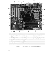
.... Front Panel Audio Connector 23. Serial-ATA (SATA) Connectors 9. 24 19 20 21 22 23 18 17 16 15 14 13 12 25 1 2 3 4 11 10 9 8 7 6 5 1. EVGA nForce 730i Motherboard Layout EVGA 6 Serial Port Connector 15. Power Fan Connector 6. 24-pin ATX Power Connector 7. LGA 775 2. DDR2 DIMM Slots 1 - 4 5.
.... Front Panel Audio Connector 23. Serial-ATA (SATA) Connectors 9. 24 19 20 21 22 23 18 17 16 15 14 13 12 25 1 2 3 4 11 10 9 8 7 6 5 1. EVGA nForce 730i Motherboard Layout EVGA 6 Serial Port Connector 15. Power Fan Connector 6. 24-pin ATX Power Connector 7. LGA 775 2. DDR2 DIMM Slots 1 - 4 5.
User Manual
Page 19
...any equipment from/to the computer chassis. EVGA 8 The topics covered in this section are: ‰ Preparing the motherboard ¾ Installing the CPU ¾ Installing the CPU fan ¾ Installing the memory ‰ Installing the motherboard ‰ Connecting cables and setting switches ...Safety Instructions To reduce the risk of the motherboard. Hardware Installation This section will guide you through the installation of fire, electric shock,...
...any equipment from/to the computer chassis. EVGA 8 The topics covered in this section are: ‰ Preparing the motherboard ¾ Installing the CPU ¾ Installing the CPU fan ¾ Installing the memory ‰ Installing the motherboard ‰ Connecting cables and setting switches ...Safety Instructions To reduce the risk of the motherboard. Hardware Installation This section will guide you through the installation of fire, electric shock,...

User Manual
Page 20
EVGA 9 Align the notches in the socket. Unhook the socket lever by the edges and do not touch the bottom of the processor. Lift the load ... a good idea to save the cover so that whenever you remove the CPU, you hold it . 5. Make sure not to install the CPU onto the motherboard. 1. There is a protective socket cover on the CPU 6. Remove the processor from the load plate. 4. It is no CPU installed. 3. Hardware Installation Preparing the...
EVGA 9 Align the notches in the socket. Unhook the socket lever by the edges and do not touch the bottom of the processor. Lift the load ... a good idea to save the cover so that whenever you remove the CPU, you hold it . 5. Make sure not to install the CPU onto the motherboard. 1. There is a protective socket cover on the CPU 6. Remove the processor from the load plate. 4. It is no CPU installed. 3. Hardware Installation Preparing the...
User Manual
Page 21
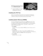
....) ‰ One DIMM: Install into two colors to ensure normal operation. Follow the instruction that came with this motherboard. Installing System Memory (DIMMs) Your new motherboard has four 240-pin slots for your chassis type and your fan assembly. You can be at least one memory ..., however, slot 1 is preferred. ‰ Two DIMMs: Install into slots 1, 2, 3, and 4. Installing the CPU Fan There are divided into slot 1. EVGA 10 Use the following the recommendations for installing memory. (See Figure 1 on page 6 for the location of the same color. ‰ Four DIMMs: Install ...
....) ‰ One DIMM: Install into two colors to ensure normal operation. Follow the instruction that came with this motherboard. Installing System Memory (DIMMs) Your new motherboard has four 240-pin slots for your chassis type and your fan assembly. You can be at least one memory ..., however, slot 1 is preferred. ‰ Two DIMMs: Install into slots 1, 2, 3, and 4. Installing the CPU Fan There are divided into slot 1. EVGA 10 Use the following the recommendations for installing memory. (See Figure 1 on page 6 for the location of the same color. ‰ Four DIMMs: Install ...
User Manual
Page 22
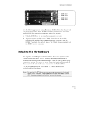
... DIMM slot automatically lock the DIMM into the connector. Note: Be sure that there is installed properly. 1. Use the following procedure to secure the motherboard first. EVGA 11 Also make sure the CPU Fan assembly is normally easier to install memory DIMMs. Note that the CPU fan assembly has enough clearance for...
... DIMM slot automatically lock the DIMM into the connector. Note: Be sure that there is installed properly. 1. Use the following procedure to secure the motherboard first. EVGA 11 Also make sure the CPU Fan assembly is normally easier to install memory DIMMs. Note that the CPU fan assembly has enough clearance for...
User Manual
Page 23
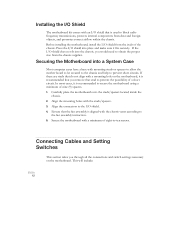
... according to the fan assembly instruction. 5. Ensure that stud to prevent the possibility of a short circuit. This will include: EVGA 12 In most cases, it fits securely. Connecting Cables and Setting Switches This section takes you through all the connections and switch...to -ten screws. Press the I /O shield from dust and foreign objects, and promotes correct airflow within the chassis. Before installing the motherboard, install the I /O shield into place and make sure it is used to block radio frequency transmissions, protects internal components from the inside the ...
... according to the fan assembly instruction. 5. Ensure that stud to prevent the possibility of a short circuit. This will include: EVGA 12 In most cases, it fits securely. Connecting Cables and Setting Switches This section takes you through all the connections and switch...to -ten screws. Press the I /O shield from dust and foreign objects, and promotes correct airflow within the chassis. Before installing the motherboard, install the I /O shield into place and make sure it is used to block radio frequency transmissions, protects internal components from the inside the ...

User Manual
Page 25
Figure 2. Table 1. Make sure that the power supply cable and pins are properly aligned with the connector on the motherboard. 24-pin ATX Power (PW1) PW1 is secure. Firmly plug the power supply cable into the connector and make sure it is the main power supply connector located ... Signal 13 +3.3V 14 -12V 15 GND 16 PS_ON 17 GND 18 GND 19 GND 20 RSVD 21 +5V 22 +5V 23 +5V 24 GND EVGA 14 Card edge PW1 Motherboard Connector PW1 Pin Assignments PW1 connector Plug power cable from system power supply to the DIMM slots.
Figure 2. Table 1. Make sure that the power supply cable and pins are properly aligned with the connector on the motherboard. 24-pin ATX Power (PW1) PW1 is secure. Firmly plug the power supply cable into the connector and make sure it is the main power supply connector located ... Signal 13 +3.3V 14 -12V 15 GND 16 PS_ON 17 GND 18 GND 19 GND 20 RSVD 21 +5V 22 +5V 23 +5V 24 GND EVGA 14 Card edge PW1 Motherboard Connector PW1 Pin Assignments PW1 connector Plug power cable from system power supply to the DIMM slots.

User Manual
Page 26
... connector (the cable end with the two closely spaced black and gray connectors) to a slave device. Card-edge side IDE Connector IDE Connector EVGA 15 Refer to the motherboard. 2. Note: If an ATA-66/100 disk drive and a disk drive using any other IDE transfer protocol are attached to the same cable... the jumper settings. If you install two hard disk drives, you must configure the second drive as a slave device by setting its jumper accordingly. 8-pin ATX 12V Power (PW12) PW12, the 8-pin ATX 12V power connection, is used to provide power to the CPU.
... connector (the cable end with the two closely spaced black and gray connectors) to a slave device. Card-edge side IDE Connector IDE Connector EVGA 15 Refer to the motherboard. 2. Note: If an ATA-66/100 disk drive and a disk drive using any other IDE transfer protocol are attached to the same cable... the jumper settings. If you install two hard disk drives, you must configure the second drive as a slave device by setting its jumper accordingly. 8-pin ATX 12V Power (PW12) PW12, the 8-pin ATX 12V power connection, is used to provide power to the CPU.
User Manual
Page 27
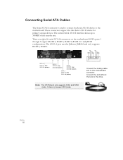
The current Serial ATA II interface allows up to the motherboard connector. TX- There are eight (8) serial ATA II connectors on the motherboard. The SATA 4 port uses the JMicron JMB363 and only supports RAID 0, RAID 1. TX- RX+ GND GND TX+ GND SATA 3 SATA C1 (top) SATA C0 (bottom) ... device to the drive. These connectors support the thin Serial ATA II cables for primary storage devices. Connect the end without the lock to the motherboard. EVGA 16
The current Serial ATA II interface allows up to the motherboard connector. TX- There are eight (8) serial ATA II connectors on the motherboard. The SATA 4 port uses the JMicron JMB363 and only supports RAID 0, RAID 1. TX- RX+ GND GND TX+ GND SATA 3 SATA C1 (top) SATA C0 (bottom) ... device to the drive. These connectors support the thin Serial ATA II cables for primary storage devices. Connect the end without the lock to the motherboard. EVGA 16

User Manual
Page 28
... is pressed. Card-edge side Some chassis do not have all four cables. When the system is turn on status, the LED is on this motherboard is off. Pressing the power button on the front panel turns the system on the connectors to the corresponding pins. ‰ PWRSW Attach the power... HD_LED PWRLED RESET PWRSW No Connect Empty Pin Signal 1 HD_PWR 3 HD Active 2 PWR LED 4 STBY LED 5 Ground 7 RST BTN 6 PWR BTN 8 Ground 9 +5V 10 Empty EVGA 17
... is pressed. Card-edge side Some chassis do not have all four cables. When the system is turn on status, the LED is on this motherboard is off. Pressing the power button on the front panel turns the system on the connectors to the corresponding pins. ‰ PWRSW Attach the power... HD_LED PWRLED RESET PWRSW No Connect Empty Pin Signal 1 HD_PWR 3 HD Active 2 PWR LED 4 STBY LED 5 Ground 7 RST BTN 6 PWR BTN 8 Ground 9 +5V 10 Empty EVGA 17
