
User Guide
Page 41
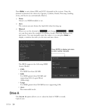
... correspond to display IDE Channel sub-menu IDE HDD Auto-Detect IDE Channel 0 Slave Access Mode Capacity Cylinder Head Precomp Landing Zone Sector [Press Enter] [Manual} [CHS] 0 MB [ 0] [ 0] [ 0] [ 0] [ 0] Capacity 0 MB Cylinder 0 Head 0 Precomp 0 Landing Zone 0 Sector 0 Using the arrow keys, position... a channel and press Enter to display the IDE/SATA sub-menu. IDE Channel 0 Master IDE Channel 0 Slave SATA 1 (A0) SATA 2 (A1) SATA 3 (B0) SATA 4 (B1) SATA 5 (C0) SATA 6 (C1) [None] [None] [None] [None] [None] [...
... correspond to display IDE Channel sub-menu IDE HDD Auto-Detect IDE Channel 0 Slave Access Mode Capacity Cylinder Head Precomp Landing Zone Sector [Press Enter] [Manual} [CHS] 0 MB [ 0] [ 0] [ 0] [ 0] [ 0] Capacity 0 MB Cylinder 0 Head 0 Precomp 0 Landing Zone 0 Sector 0 Using the arrow keys, position... a channel and press Enter to display the IDE/SATA sub-menu. IDE Channel 0 Master IDE Channel 0 Slave SATA 1 (A0) SATA 2 (A1) SATA 3 (B0) SATA 4 (B1) SATA 5 (C0) SATA 6 (C1) [None] [None] [None] [None] [None] [...
User Guide
Page 42
... not supporting LBA. Auto Recommended mode. IDE HDD Auto-Detect [Press Enter] IDE Channel 0 Slave Access Mode Capacity Cylinder Head Precomp Landing Zone Sector [Manual} [CHS] 0 MB .....0 [ 0] [ 0] [ 0] [ 0] Press ENTER to auto-detect IDE and SATA channels in . None There is no HDD installed or ...install. Options are automatically filled in the system. ESC:Abort The Drive A option allows you the min and max values. You can manually enter the values or you can then enter the number of FDD to select the kind of cylinders, heads, Precomp, landing zone, and...
... not supporting LBA. Auto Recommended mode. IDE HDD Auto-Detect [Press Enter] IDE Channel 0 Slave Access Mode Capacity Cylinder Head Precomp Landing Zone Sector [Manual} [CHS] 0 MB .....0 [ 0] [ 0] [ 0] [ 0] Press ENTER to auto-detect IDE and SATA channels in . None There is no HDD installed or ...install. Options are automatically filled in the system. ESC:Abort The Drive A option allows you the min and max values. You can manually enter the values or you can then enter the number of FDD to select the kind of cylinders, heads, Precomp, landing zone, and...
User Guide
Page 55
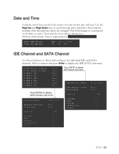
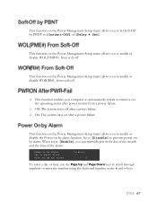
...#) from a power failure. Off: The system stays off . This function on the Power Management Setup menu allows you to set to [Enable], you can manually put in the day of the month and the time of Month Alarm Time (hh:mm:ss) Alarm [Disabled] [ 0] [0 : 0 : 0] To enter a day or time, use...
...#) from a power failure. Off: The system stays off . This function on the Power Management Setup menu allows you to set to [Enable], you can manually put in the day of the month and the time of Month Alarm Time (hh:mm:ss) Alarm [Disabled] [ 0] [0 : 0 : 0] To enter a day or time, use...
User Guide
Page 58
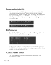
... item is enabled for devices compliant with the plug-and-play compatible devices or if you can assign the resources, IRQ Resources is designed to [Manual]. With this field for devices compliant with the original PC AT Bus specification. IRQ-5 assigned to IRQ-9 assigned to IRQ-10 assigned to IRQ-...Use PCI/ISA PnP for input, set Resources Controlled By to overcome problems that may be caused by some nonstandard VGA cards.. If you select [Manual] so you want the BIOS to see options. Resources Controlled By [Auto(ESCD)] x IRQ Resources Press Enter Resources Controlled By...
... item is enabled for devices compliant with the plug-and-play compatible devices or if you can assign the resources, IRQ Resources is designed to [Manual]. With this field for devices compliant with the original PC AT Bus specification. IRQ-5 assigned to IRQ-9 assigned to IRQ-10 assigned to IRQ-...Use PCI/ISA PnP for input, set Resources Controlled By to overcome problems that may be caused by some nonstandard VGA cards.. If you select [Manual] so you want the BIOS to see options. Resources Controlled By [Auto(ESCD)] x IRQ Resources Press Enter Resources Controlled By...
User Guide
Page 61
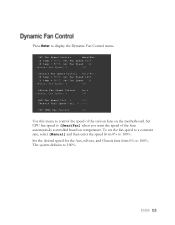
...100 Chassis Fan Speed Control [SmartFan] If temp > 70ºC, Set Fan Speed 100% If temp < 30ºC, Set Fan Speed 1% x Manual Fan Speed, % 100 nForce Fan Speed Control [Auto] x Manual Fan Speed, % 100 AUX Fan Speed Ctrl, % [100] Chassis Fan2 Speed Ctrl, % [100] CPU VREG Fan Control [on] Use this...CPU fan speed to control the speed of the fans automatically controlled based on the motherboard. To set the fan speed to a constant rate, select [Manual] and then enter the speed from 0% to 100%. Press Enter to 100%. Set the desired speed for the Aux, nForce, and Chassis fans ...
...100 Chassis Fan Speed Control [SmartFan] If temp > 70ºC, Set Fan Speed 100% If temp < 30ºC, Set Fan Speed 1% x Manual Fan Speed, % 100 nForce Fan Speed Control [Auto] x Manual Fan Speed, % 100 AUX Fan Speed Ctrl, % [100] Chassis Fan2 Speed Ctrl, % [100] CPU VREG Fan Control [on] Use this...CPU fan speed to control the speed of the fans automatically controlled based on the motherboard. To set the fan speed to a constant rate, select [Manual] and then enter the speed from 0% to 100%. Press Enter to 100%. Set the desired speed for the Aux, nForce, and Chassis fans ...
User Guide
Page 66
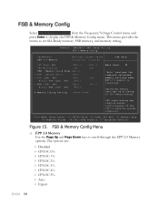
... "Auto" realizes the complete optimized memory settings when EPP 2.0 memory is installed Optimized memory settings by allowing X% CPU overclocking CPU overclocking may require manual overvoltaging of the CPU to set SLI-Ready memory, FSB memory, and memory timing. This menu provides the means to improve system stability Move Enter...
... "Auto" realizes the complete optimized memory settings when EPP 2.0 memory is installed Optimized memory settings by allowing X% CPU overclocking CPU overclocking may require manual overvoltaging of the CPU to set SLI-Ready memory, FSB memory, and memory timing. This menu provides the means to improve system stability Move Enter...
User Guide
Page 67
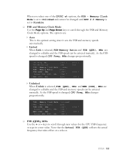
... Mode is set to Disable. FSB and Memory Clock Mode Use the Page Up and Page Down keys to Unlinked and cannot be entered manually. When you select one of the CPUOC x% options, the FSB - As the FSB speed is changed to editable and the FSB speed can be entered...
... Mode is set to Disable. FSB and Memory Clock Mode Use the Page Up and Page Down keys to Unlinked and cannot be entered manually. When you select one of the CPUOC x% options, the FSB - As the FSB speed is changed to editable and the FSB speed can be entered...
User Guide
Page 68
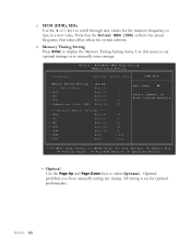
.... Memory Timing Setting Press Enter to scroll through new values for optimal performance. Optimal prohibits you from manually setting any timing. All timing is set optimal timings or to manually enter timings. Use this menu to select Optimal. MEM (DDR), MHz Use the + or - ...21) x tREF Auto x tRFC Auto 7 7 7 20 1T 4 27 10 14 21 7.8uS 110ns Main Level Select [Expert] to enter timings manually Move Enter:Select +/-/PU/PD:Value F10:Save ESC:Exit F1:General Help F5:Previous Values F6:Fail-Safe Defaults F7:Optimized Defaults Optimal...
.... Memory Timing Setting Press Enter to scroll through new values for optimal performance. Optimal prohibits you from manually setting any timing. All timing is set optimal timings or to manually enter timings. Use this menu to select Optimal. MEM (DDR), MHz Use the + or - ...21) x tREF Auto x tRFC Auto 7 7 7 20 1T 4 27 10 14 21 7.8uS 110ns Main Level Select [Expert] to enter timings manually Move Enter:Select +/-/PU/PD:Value F10:Save ESC:Exit F1:General Help F5:Previous Values F6:Fail-Safe Defaults F7:Optimized Defaults Optimal...

User Guide
Page 69
... Expert is the minimum RAS# active time (options are Auto and 1 through 31). Command Per Clock: This is the minimum write-to -CAS# Delay for manual input. tRCD: RAS#-to -read delay with the same chip selected (options are Auto and 5 through 15). Parameters Settings Current Value Memory Timing Setting tCL...
... Expert is the minimum RAS# active time (options are Auto and 1 through 31). Command Per Clock: This is the minimum write-to -CAS# Delay for manual input. tRCD: RAS#-to -read delay with the same chip selected (options are Auto and 5 through 15). Parameters Settings Current Value Memory Timing Setting tCL...
User Guide
Page 75
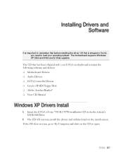
... My Computer and click on the install screen. The CD will autorun, install the drivers and utilities listed on the CD to load your EVGA motherboard contains the following software and drivers: Motherboard Drivers Audio Drivers SATA Controller Drivers Create a RAID... Floppy Disk Adobe Acrobat Reader® View CD Manual Insert the EVGA nForce 790i SLI FTW installation CD in the kit, you need to open. It is important to remember that before installing the driver CD...
... My Computer and click on the install screen. The CD will autorun, install the drivers and utilities listed on the CD to load your EVGA motherboard contains the following software and drivers: Motherboard Drivers Audio Drivers SATA Controller Drivers Create a RAID... Floppy Disk Adobe Acrobat Reader® View CD Manual Insert the EVGA nForce 790i SLI FTW installation CD in the kit, you need to open. It is important to remember that before installing the driver CD...
Visual Guide
Page 2
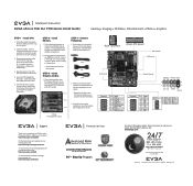
.... Lower the CPU straight into the socket. Install Memory 1. Install Graphics Card(s) 1. GPU 1 GPU 2 GPU 3 STEP 4 - EVGA 714 . 528. 4500 www.evga.com/support *24/7 North America only *Not all Premium Services apply to the manual that are installing a single graphics card use DIMM slots 0 and 1, 2 and 3, or 0 through 3. Align the notches in...
.... Lower the CPU straight into the socket. Install Memory 1. Install Graphics Card(s) 1. GPU 1 GPU 2 GPU 3 STEP 4 - EVGA 714 . 528. 4500 www.evga.com/support *24/7 North America only *Not all Premium Services apply to the manual that are installing a single graphics card use DIMM slots 0 and 1, 2 and 3, or 0 through 3. Align the notches in...
