
User Guide
Page 12
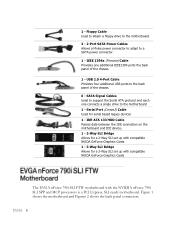
... USB ports to a SATA power connector. 1 - Floppy Cable Used to attach a floppy drive to the motherboard. 3 - 2-Port SATA Power Cables Allows a Molex power connector to adapt to the back panel of the chassis. 1 - SATA Signal Cables Used to the motherboard 1 - Serial Port (Comm2) Cable Used for a 3-Way SLI set up with compatible NVIDA GeForce Graphics Cards The EVGA nForce 790i SLI FTW motherboard with the NVIDIA nForce 790i SLI SPP and MCP processors is a PCI Express, SLI-ready motherboard. IEEE 1394a (Firewire) Cable Provides one connects a single drive to support the Serial...
... USB ports to a SATA power connector. 1 - Floppy Cable Used to attach a floppy drive to the motherboard. 3 - 2-Port SATA Power Cables Allows a Molex power connector to adapt to the back panel of the chassis. 1 - SATA Signal Cables Used to the motherboard 1 - Serial Port (Comm2) Cable Used for a 3-Way SLI set up with compatible NVIDA GeForce Graphics Cards The EVGA nForce 790i SLI FTW motherboard with the NVIDIA nForce 790i SLI SPP and MCP processors is a PCI Express, SLI-ready motherboard. IEEE 1394a (Firewire) Cable Provides one connects a single drive to support the Serial...
User Guide
Page 13
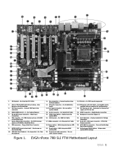
... System Memory 5. 24-pin ATX power connector - IDE connector - FDD connector - For Serial Port Cable 15. PCI Express x16 slots (SLI) - MCP/SPP fan connector - Motherboard CMOS Battery - Power button - Digital Audio connection 25. CPU 8-Pin Power connector 28. For IDE devices such as a CD-ROM or Hard Disk Drive 8. For Hi-Definition Audio 13. Serial connector - With integrated power LED indicator 19. USB headers - Passive heatsink for SLI configurations 23. Helps retain system BIOS settings Figure 1. Connect CPU Fan to these headers 12. LED POST Code Readout...
... System Memory 5. 24-pin ATX power connector - IDE connector - FDD connector - For Serial Port Cable 15. PCI Express x16 slots (SLI) - MCP/SPP fan connector - Motherboard CMOS Battery - Power button - Digital Audio connection 25. CPU 8-Pin Power connector 28. For IDE devices such as a CD-ROM or Hard Disk Drive 8. For Hi-Definition Audio 13. Serial connector - With integrated power LED indicator 19. USB headers - Passive heatsink for SLI configurations 23. Helps retain system BIOS settings Figure 1. Connect CPU Fan to these headers 12. LED POST Code Readout...
User Guide
Page 19
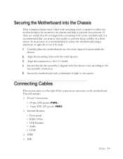
... to allow the mother board to be secured to the chassis and help to prevent short circuits. This will include: Power Connections 24-pin ATX power (PWR1) 8-pin ATX 12V power (PWR2) Internal Headers Front panel IEEE 1394a USB Headers Audio COM FDD IDE This section takes you remove that the fan assembly is recommended to secure the motherboard using a minimum of...
... to allow the mother board to be secured to the chassis and help to prevent short circuits. This will include: Power Connections 24-pin ATX power (PWR1) 8-pin ATX 12V power (PWR2) Internal Headers Front panel IEEE 1394a USB Headers Audio COM FDD IDE This section takes you remove that the fan assembly is recommended to secure the motherboard using a minimum of...

User Guide
Page 38
... menu to monitor the real-time system status of your PC, including temperature, voltages, and fan speed. AwardBIOS CMOS Setup Utility Standard CMOS Features Advanced BIOS Features Advanced Chipset Features Integrated Peripherals Power Management Setup PnP/PCI Configurations PC Health Status Esc : Quit F10 : Save & Exit Setup Frequency/Voltage Control Load Fail-Safe Defaults Load Optimized Defaults Set Supervisor Password Set User Password Save & Exit Setup Exit Without Saving Select Item Time, Date, Hard Disk Type...
... menu to monitor the real-time system status of your PC, including temperature, voltages, and fan speed. AwardBIOS CMOS Setup Utility Standard CMOS Features Advanced BIOS Features Advanced Chipset Features Integrated Peripherals Power Management Setup PnP/PCI Configurations PC Health Status Esc : Quit F10 : Save & Exit Setup Frequency/Voltage Control Load Fail-Safe Defaults Load Optimized Defaults Set Supervisor Password Set User Password Save & Exit Setup Exit Without Saving Select Item Time, Date, Hard Disk Type...
User Guide
Page 41
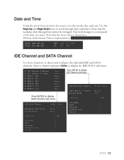
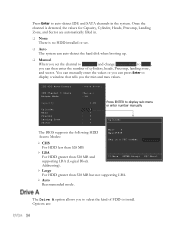
... field changes to correspond to display IDE Channel sub-menu IDE HDD Auto-Detect IDE Channel 0 Slave Access Mode Capacity Cylinder Head Precomp Landing Zone Sector [Press Enter] [Manual} [CHS] 0 MB [ 0] [ 0] [ 0] [ 0] [ 0] Capacity 0 MB Cylinder 0 Head 0 Precomp 0 Landing Zone 0 Sector 0 Using the arrow keys, position the cursor over the month, day, and year. Select a channel and press Enter to display the IDE/SATA sub-menu. IDE Channel 0 Master IDE Channel 0 Slave SATA 1 (A0) SATA 2 (A1) SATA...
... field changes to correspond to display IDE Channel sub-menu IDE HDD Auto-Detect IDE Channel 0 Slave Access Mode Capacity Cylinder Head Precomp Landing Zone Sector [Press Enter] [Manual} [CHS] 0 MB [ 0] [ 0] [ 0] [ 0] [ 0] Capacity 0 MB Cylinder 0 Head 0 Precomp 0 Landing Zone 0 Sector 0 Using the arrow keys, position the cursor over the month, day, and year. Select a channel and press Enter to display the IDE/SATA sub-menu. IDE Channel 0 Master IDE Channel 0 Slave SATA 1 (A0) SATA 2 (A1) SATA...
User Guide
Page 42
... min and max values. Options are automatically filled in. None There is detected, the values for Capacity, Cylinder, Heads, Precomp, Landing Zone, and Sector are : Once the channel is no HDD installed or set. Auto The system can auto-detect the hard disk when booting up. Manual When you set the channel to [Manual] and change Access Mode to [CHS], you can press Enter to display a window that...
... min and max values. Options are automatically filled in. None There is detected, the values for Capacity, Cylinder, Heads, Precomp, Landing Zone, and Sector are : Once the channel is no HDD installed or set. Auto The system can auto-detect the hard disk when booting up. Manual When you set the channel to [Manual] and change Access Mode to [CHS], you can press Enter to display a window that...
User Guide
Page 46
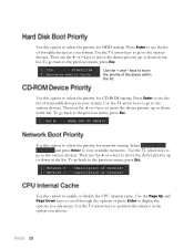
...-ROM startup. Select Network Boot Priority and press Enter to the previous menu, press Esc. 1. Then use the + or - keys to move the device priority up or down in the list. keys to move the device priority up or down in the list. keys to the previous menu, press Esc. 1. To go back to view available networks. Use the arrow keys to display the options in a sub-menu...
...-ROM startup. Select Network Boot Priority and press Enter to the previous menu, press Esc. 1. Then use the + or - keys to move the device priority up or down in the list. keys to move the device priority up or down in the list. keys to the previous menu, press Esc. 1. To go back to view available networks. Use the arrow keys to display the options in a sub-menu...
User Guide
Page 47
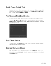
... and Page Down keys to display the sub-menu. Use the Page Up and Page Down keys to scroll through the options or press Enter to toggle between Enable and Disable. First Boot Device Removable Hard Disk CDROM Network Disabled :Move ENTER:Accept ESC:Abort With the option set the priority sequence of the devices booted at power on state of NumLock. Select On to Enable, the system boots from some other...
... and Page Down keys to display the sub-menu. Use the Page Up and Page Down keys to scroll through the options or press Enter to toggle between Enable and Disable. First Boot Device Removable Hard Disk CDROM Network Disabled :Move ENTER:Accept ESC:Abort With the option set the priority sequence of the devices booted at power on state of NumLock. Select On to Enable, the system boots from some other...
User Guide
Page 49
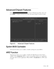
... CMOS Setup Utility Advanced Chipset Features System BIOS Cacheable HPET Function [Disabled] [Enable] Item Help Main Level Move Enter:Select +/-/PU/PD:Value F10:Save ESC:Exit F1:General Help F5:Previous Values F6:Fail-Safe Defaults F7:Optimized Defaults Figure 8. When HPET is Disabled, the APIC timer is used . Advanced Chipset Features This function allows you to display the functions of the Advanced Chipset Functions menu...
... CMOS Setup Utility Advanced Chipset Features System BIOS Cacheable HPET Function [Disabled] [Enable] Item Help Main Level Move Enter:Select +/-/PU/PD:Value F10:Save ESC:Exit F1:General Help F5:Previous Values F6:Fail-Safe Defaults F7:Optimized Defaults Figure 8. When HPET is Disabled, the APIC timer is used . Advanced Chipset Features This function allows you to display the functions of the Advanced Chipset Functions menu...

User Guide
Page 50
...; IDE Function Setup RAID Config USB Config MAC Config IEEE 1394 Controller JMicron AHCI (SATA 7/8) JMicron AHCI (SATA 9/10) HD Audio Onboard FDC controller Onboard Serial Port 1 [Press Enter] [Press Enter] [Press Enter] [Press Enter] [Enabled] [Enabled] [Enabled] [Auto] [Enabled] [3F8/IRQ4] Item Help Main Level Move Enter:Select +/-/PU/PD:Value F10:Save ESC:Exit F1:General Help F5:Previous Values F6:Fail-Safe Defaults F7:Optimized Defaults Figure 9. Select Integrated Peripherals from the CMOS Setup Utility menu and press Enter to display...
...; IDE Function Setup RAID Config USB Config MAC Config IEEE 1394 Controller JMicron AHCI (SATA 7/8) JMicron AHCI (SATA 9/10) HD Audio Onboard FDC controller Onboard Serial Port 1 [Press Enter] [Press Enter] [Press Enter] [Press Enter] [Enabled] [Enabled] [Enabled] [Auto] [Enabled] [3F8/IRQ4] Item Help Main Level Move Enter:Select +/-/PU/PD:Value F10:Save ESC:Exit F1:General Help F5:Previous Values F6:Fail-Safe Defaults F7:Optimized Defaults Figure 9. Select Integrated Peripherals from the CMOS Setup Utility menu and press Enter to display...

User Guide
Page 51
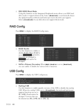
... options available are changed to enable specific SATA controllers. When disabled, the Primary Master/Slave functions are [SATA-0], [SATA-0+1], [Enabled], and [Disabled]. IDE Prefetch Mode Use this function to enable or disable the IDE Prefetch mode. Press Enter to [Enabled], you can select a mode for the primary Master and Slave PIO. OnChip IDE Channel0 Primary Master PIO Primary Slave PIO Primary Master UDMA Primary Slave UDMA IDE DMA transfer access Serial-ATA Controller IDE Prefetch Mode IDE HDD Block Mode [Enabled] [Auto] [Auto] [Auto] [Auto] [Enabled...
... options available are changed to enable specific SATA controllers. When disabled, the Primary Master/Slave functions are [SATA-0], [SATA-0+1], [Enabled], and [Disabled]. IDE Prefetch Mode Use this function to enable or disable the IDE Prefetch mode. Press Enter to [Enabled], you can select a mode for the primary Master and Slave PIO. OnChip IDE Channel0 Primary Master PIO Primary Slave PIO Primary Master UDMA Primary Slave UDMA IDE DMA transfer access Serial-ATA Controller IDE Prefetch Mode IDE HDD Block Mode [Enabled] [Auto] [Auto] [Auto] [Auto] [Enabled...
User Guide
Page 52
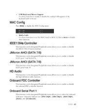
...be OnChip USB x USB Keyboard Support [Disabled] Enabled changed. OnChip USB USB Keyboard Support USB Mouse Support [V1.1+V2.0] [Enabled] [Enabled] OnChip USB Use this function to enable specific versions of block read/writes per sector the drive can x USB Mouse Support Enabled be changed to support block mode. Select [Disabled] if your IDE hard drive needs to Disabled and cannot be selected are set to [Enabled], you can enable or disable the various SATA functions. Press Enter to display the USB Config menu. RAID Enable x SATA 1 (A0) RAID x SATA 2 (A1) RAID x SATA...
...be OnChip USB x USB Keyboard Support [Disabled] Enabled changed. OnChip USB USB Keyboard Support USB Mouse Support [V1.1+V2.0] [Enabled] [Enabled] OnChip USB Use this function to enable specific versions of block read/writes per sector the drive can x USB Mouse Support Enabled be changed to support block mode. Select [Disabled] if your IDE hard drive needs to Disabled and cannot be selected are set to [Enabled], you can enable or disable the various SATA functions. Press Enter to display the USB Config menu. RAID Enable x SATA 1 (A0) RAID x SATA 2 (A1) RAID x SATA...
User Guide
Page 53
... enable or disable the IEEE 1394a (Firewire) interface. This function on the Integrated Peripherals menu allows you to enable or disable the onchip USB support of the keyboard and/or mouse. MAC0 LAN MAC1 LAN [Auto] [Auto] MACx LAN Use these function to enable or disable the onboard FDC controller function. Press Enter to select the onboard serial port 1 function. This function on the Integrated Peripherals menu allows you to display the MAC Config menu...
... enable or disable the IEEE 1394a (Firewire) interface. This function on the Integrated Peripherals menu allows you to enable or disable the onchip USB support of the keyboard and/or mouse. MAC0 LAN MAC1 LAN [Auto] [Auto] MACx LAN Use these function to enable or disable the onboard FDC controller function. Press Enter to select the onboard serial port 1 function. This function on the Integrated Peripherals menu allows you to display the MAC Config menu...

User Guide
Page 54
...:mm:ss) Alarm [Disabled] 0 0 : 0 : 0 POWER ON Function x KB Power ON Password x Hot Key Power On [BUTTON ONLY] Enter Ctrl-F1 Move Enter:Select +/-/PU/PD:Value F10:Save ESC:Exit F1:General Help F5:Previous Values F6:Fail-Safe Defaults F7:Optimized Defaults Figure 10. Types to select from the CMOS Setup Utility menu and press Enter to display the Power Management Setup menu. This function on by PBTN WOL(PME#) From Soft...
...:mm:ss) Alarm [Disabled] 0 0 : 0 : 0 POWER ON Function x KB Power ON Password x Hot Key Power On [BUTTON ONLY] Enter Ctrl-F1 Move Enter:Select +/-/PU/PD:Value F10:Save ESC:Exit F1:General Help F5:Previous Values F6:Fail-Safe Defaults F7:Optimized Defaults Figure 10. Types to select from the CMOS Setup Utility menu and press Enter to display the Power Management Setup menu. This function on by PBTN WOL(PME#) From Soft...
User Guide
Page 57
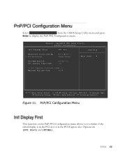
Options are [PCI Slot] and [PCIEx]. Phoenix - AwardBIOS CMOS Setup Utility PnP/PCI Configuration Init Display First [PCI Slot] Item Help Resources Controlled By x IRQ Resources [Auto(ESCD)] Press Enter Main Level PCI/VGA Palette PCI Latency Timer(CLK) [Disabled] [32] ** PCI Express relative items ** Maximum Payload Size [4096] Move Enter:Select +/-/PU/PD:Value F10:Save ESC:Exit F1:General Help F5:Previous Values F6:Fail-Safe Defaults F7:Optimized Defaults Figure 11. PnP/PCI Configuration Menu This...
Options are [PCI Slot] and [PCIEx]. Phoenix - AwardBIOS CMOS Setup Utility PnP/PCI Configuration Init Display First [PCI Slot] Item Help Resources Controlled By x IRQ Resources [Auto(ESCD)] Press Enter Main Level PCI/VGA Palette PCI Latency Timer(CLK) [Disabled] [32] ** PCI Express relative items ** Maximum Payload Size [4096] Move Enter:Select +/-/PU/PD:Value F10:Save ESC:Exit F1:General Help F5:Previous Values F6:Fail-Safe Defaults F7:Optimized Defaults Figure 11. PnP/PCI Configuration Menu This...
User Guide
Page 60
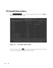
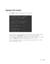
Phoenix - AwardBIOS CMOS Setup Utility PC Health Status Dynamic Fan Control CPU Board MCP55 [Press Enter] 38ºC/ 100ºF 42ºC/ 108ºF 59ºC/ 138ºF Item Help Main Level CPU Core +5V Memory nForce SPP +3.3V +12V +Vbat 1.27V 4.97V 1.48V 1.31V 3.21V 11.91V 3.02V CPU Fan Speed Chassis Fan Speed Chassis Fan2 Speed Aux Fan Speed nForce Fan Speed 4272 RPM 0 RPM 0 RPM 4891 RPM 0 RPM Move Enter:Select...
Phoenix - AwardBIOS CMOS Setup Utility PC Health Status Dynamic Fan Control CPU Board MCP55 [Press Enter] 38ºC/ 100ºF 42ºC/ 108ºF 59ºC/ 138ºF Item Help Main Level CPU Core +5V Memory nForce SPP +3.3V +12V +Vbat 1.27V 4.97V 1.48V 1.31V 3.21V 11.91V 3.02V CPU Fan Speed Chassis Fan Speed Chassis Fan2 Speed Aux Fan Speed nForce Fan Speed 4272 RPM 0 RPM 0 RPM 4891 RPM 0 RPM Move Enter:Select...
User Guide
Page 61
...ºC, Set Fan Speed 1% x Manual Fan Speed, % 100 nForce Fan Speed Control [Auto] x Manual Fan Speed, % 100 AUX Fan Speed Ctrl, % [100] Chassis Fan2 Speed Ctrl, % [100] CPU VREG Fan Control [on] Use this menu to display the Dynamic Fan Control menu. Press Enter to control the speed of the fans automatically controlled based on temperature. Set the desired speed for the Aux, nForce, and Chassis fans from 0% to 100%. The system defaults to [SmartFan] when you want the speed of the various fans on the motherboard. To set the fan speed to...
...ºC, Set Fan Speed 1% x Manual Fan Speed, % 100 nForce Fan Speed Control [Auto] x Manual Fan Speed, % 100 AUX Fan Speed Ctrl, % [100] Chassis Fan2 Speed Ctrl, % [100] CPU VREG Fan Control [on] Use this menu to display the Dynamic Fan Control menu. Press Enter to control the speed of the fans automatically controlled based on temperature. Set the desired speed for the Aux, nForce, and Chassis fans from 0% to 100%. The system defaults to [SmartFan] when you want the speed of the various fans on the motherboard. To set the fan speed to...
User Guide
Page 64
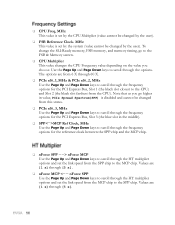
... frequency options for the PCI Express Bus, Slot 3 (the blue slot in value, PCIe Spread Spectrum(SPP) is set by the CPU Multiplier (value cannot be changed by the user). MHz This value is set the link speed from the CPU). Use the Page Up and Page Down keys to scroll through the frequency options for the reference clock between the SPP chip and the MCP chip. nForce SPP - -> nForce MCP Use...
... frequency options for the PCI Express Bus, Slot 3 (the blue slot in value, PCIe Spread Spectrum(SPP) is set by the CPU Multiplier (value cannot be changed by the user). MHz This value is set the link speed from the CPU). Use the Page Up and Page Down keys to scroll through the frequency options for the reference clock between the SPP chip and the MCP chip. nForce SPP - -> nForce MCP Use...

User Guide
Page 83
Write all CMOS values back to RAM and clear screen. Display PNP devices Final USB initialization Setup ACPI tables Scan for user intervention Ask password security. HDD check for write protection Check POST error and display them and ask for Option ROMs Enable Parity Check Initialize parallel ports. Code 75 76 77 78 79 7A 7B 7C 7D 7E 7F 80 81 82 83 84 85 86 87 88 89 8A...
Write all CMOS values back to RAM and clear screen. Display PNP devices Final USB initialization Setup ACPI tables Scan for user intervention Ask password security. HDD check for write protection Check POST error and display them and ask for Option ROMs Enable Parity Check Initialize parallel ports. Code 75 76 77 78 79 7A 7B 7C 7D 7E 7F 80 81 82 83 84 85 86 87 88 89 8A...
Visual Guide
Page 2
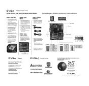
...Cables Floppy IDE SATA 2. Align the notches in 2 Dimm Mode * Use matching color slots for dual channel STEP 3 - Install Memory 1. Having matched pairs is no CPU installed. 3. GND GND TPB+ TPB+12V +12V Empty GND Connector Pin Signal Pin Signal USB 2.0 Header 1 Connector 3 9 10 5 7 7 8 9 5V_DUAL 2 D- 4 D+ 6 GND 8 Empty 10 5V_DUAL DD+ GND No Connect 5 6 3 4 1 2 Support Thank you for detailed instructions. There is a protective socket cover on the socket. 5. STEP 2 - Now connect your peripheral devices such as hard drives, floppy drive, and DVD-ROM...
...Cables Floppy IDE SATA 2. Align the notches in 2 Dimm Mode * Use matching color slots for dual channel STEP 3 - Install Memory 1. Having matched pairs is no CPU installed. 3. GND GND TPB+ TPB+12V +12V Empty GND Connector Pin Signal Pin Signal USB 2.0 Header 1 Connector 3 9 10 5 7 7 8 9 5V_DUAL 2 D- 4 D+ 6 GND 8 Empty 10 5V_DUAL DD+ GND No Connect 5 6 3 4 1 2 Support Thank you for detailed instructions. There is a protective socket cover on the socket. 5. STEP 2 - Now connect your peripheral devices such as hard drives, floppy drive, and DVD-ROM...


