User Guide
Page 1
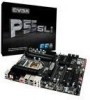
User's Guide EVGA P55 SLI Motherboard
User's Guide EVGA P55 SLI Motherboard
User Guide
Page 3
... Kit 7 EVGA P55 SLI Motherboard 8 Motherboard Specifications 8 Hardware Installation 10 Safety Instructions 10 Preparing the Motherboard 11 Installing the CPU 11 Installing the CPU Fan 12 Installing System Memory (DIMMs 13 Installing the Motherboard 13 Installing the I/O Shield 14 Securing the Motherboard into a System Case 15 Connecting Cables 15 24-pin ATX Power (PW1 16 8-pin ATX 12V Power...
... Kit 7 EVGA P55 SLI Motherboard 8 Motherboard Specifications 8 Hardware Installation 10 Safety Instructions 10 Preparing the Motherboard 11 Installing the CPU 11 Installing the CPU Fan 12 Installing System Memory (DIMMs 13 Installing the Motherboard 13 Installing the I/O Shield 14 Securing the Motherboard into a System Case 15 Connecting Cables 15 24-pin ATX Power (PW1 16 8-pin ATX 12V Power...
User Guide
Page 5
POST Codes for the EVGA P55 SLI Motherboard 42 Assertion Width 38 Restore on AC Power Loss 38 Hardware Health Configure 38 H/W Health Function 38 CPU Fan Mode Setting 39 Frequency/Voltage Control Menu 39 Memory Configure 39 CPU Configuration 40 Installing Drivers and Software 41 Windows XP/Vista/7 Driver Installation 41 Appendix A. EVGA P55 SLI Motherboard Palette Snooping 35 PCI IDE BusMaster 35 OffBoard PCI/ISA IDE Card 35 Boot Configuration Features 36 Boot Device Priority 36 Hard Disk Drives 36 Power Management Features 37 ACPI Configuration 37 SLP_S4# Min.
POST Codes for the EVGA P55 SLI Motherboard 42 Assertion Width 38 Restore on AC Power Loss 38 Hardware Health Configure 38 H/W Health Function 38 CPU Fan Mode Setting 39 Frequency/Voltage Control Menu 39 Memory Configure 39 CPU Configuration 40 Installing Drivers and Software 41 Windows XP/Vista/7 Driver Installation 41 Appendix A. EVGA P55 SLI Motherboard Palette Snooping 35 PCI IDE BusMaster 35 OffBoard PCI/ISA IDE Card 35 Boot Configuration Features 36 Boot Device Priority 36 Hard Disk Drives 36 Power Management Features 37 ACPI Configuration 37 SLP_S4# Min.
User Guide
Page 6
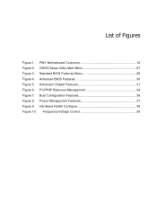
Advanced BIOS Features 30 Figure 5. Hardware Health Configure 38 Figure 10. List of Figures Figure 1. CMOS Setup Utility Main Menu 27 Figure 3. Advanced Chipset Features 31 Figure 6. Boot Configuration Features 36 Figure 8. PCI/PNP Resource Management 34 Figure 7. Power Management Features 37 Figure 9. Frequency/Voltage Control 39 Standard BIOS Features Menu 28 Figure 4. PW1 Motherboard Connector 16 Figure 2.
Advanced BIOS Features 30 Figure 5. Hardware Health Configure 38 Figure 10. List of Figures Figure 1. CMOS Setup Utility Main Menu 27 Figure 3. Advanced Chipset Features 31 Figure 6. Boot Configuration Features 36 Figure 8. PCI/PNP Resource Management 34 Figure 7. Power Management Features 37 Figure 9. Frequency/Voltage Control 39 Standard BIOS Features Menu 28 Figure 4. PW1 Motherboard Connector 16 Figure 2.
User Guide
Page 7
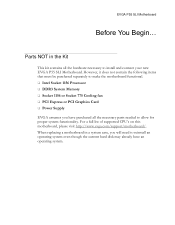
For a full list of supported CPU's on this motherboard, please visit http://www.evga.com/support/motherboard/. When replacing a motherboard in the Kit This kit contains all the hardware necessary to reinstall an operating system even though the current ...to make the motherboard functional. Intel Socket 1156 Processor DDR3 System Memory Socket 1156 or Socket 775 Cooling fan PCI Express or PCI Graphics Card Power Supply EVGA assumes you will need to install and connect your new EVGA P55 SLI Motherboard. EVGA P55 SLI Motherboard Before You ...
For a full list of supported CPU's on this motherboard, please visit http://www.evga.com/support/motherboard/. When replacing a motherboard in the Kit This kit contains all the hardware necessary to reinstall an operating system even though the current ...to make the motherboard functional. Intel Socket 1156 Processor DDR3 System Memory Socket 1156 or Socket 775 Cooling fan PCI Express or PCI Graphics Card Power Supply EVGA assumes you will need to install and connect your new EVGA P55 SLI Motherboard. EVGA P55 SLI Motherboard Before You ...
User Guide
Page 8
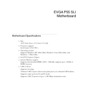
EVGA P55 SLI Motherboard Motherboard Specifications Size ATX form factor of DDR3 memory. USB 2.0 Ports Supports hot plug Thirteen USB 2.0 ports (Seven rear panel ports, six onboard USB headers) Supports wake-up ... Processor support Intel Socket 1156 CPU's Operating systems: Supports Windows XP 32bit/64bit, Windows Vista 32bit/64bit, and Windows 7 32bit/64bit Intel P55 Express Chipset System Memory support Supports dual channel DDR3-1600+.
EVGA P55 SLI Motherboard Motherboard Specifications Size ATX form factor of DDR3 memory. USB 2.0 Ports Supports hot plug Thirteen USB 2.0 ports (Seven rear panel ports, six onboard USB headers) Supports wake-up ... Processor support Intel Socket 1156 CPU's Operating systems: Supports Windows XP 32bit/64bit, Windows Vista 32bit/64bit, and Windows 7 32bit/64bit Intel P55 Express Chipset System Memory support Supports dual channel DDR3-1600+.
User Guide
Page 10
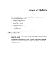
Hardware Installation This section will guide you through the installation of fire, electric shocks, and injury, always follow basic safety precautions. Remember to remove power off your computer by disconnecting the AC main source before removing or installing any equipment from/to the computer chassis. The topics covered in this section are: Preparing the motherboard Installing the CPU Installing the CPU fan Installing the memory Installing the motherboard Connecting cables Safety Instructions To reduce the risk of the motherboard.
Hardware Installation This section will guide you through the installation of fire, electric shocks, and injury, always follow basic safety precautions. Remember to remove power off your computer by disconnecting the AC main source before removing or installing any equipment from/to the computer chassis. The topics covered in this section are: Preparing the motherboard Installing the CPU Installing the CPU fan Installing the memory Installing the motherboard Connecting cables Safety Instructions To reduce the risk of the motherboard.
User Guide
Page 11
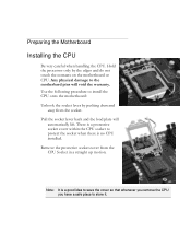
... installed. Any physical damage to store it. Use the following procedure to install the CPU onto the motherboard: Unhook the socket lever by the edges and do not touch the contacts on the motherboard or CPU. Remove the protective socket cover from the socket. Pull the socket lever back and the...idea to save the cover so that whenever you remove the CPU you have a safe place to the motherbard pins will automatically lift. Preparing the Motherboard Installing the CPU Be very careful when handling the CPU. Hold the processor only by pushing down and away from the CPU Socket in a straight...
... installed. Any physical damage to store it. Use the following procedure to install the CPU onto the motherboard: Unhook the socket lever by the edges and do not touch the contacts on the motherboard or CPU. Remove the protective socket cover from the socket. Pull the socket lever back and the...idea to save the cover so that whenever you remove the CPU you have a safe place to the motherbard pins will automatically lift. Preparing the Motherboard Installing the CPU Be very careful when handling the CPU. Hold the processor only by pushing down and away from the CPU Socket in a straight...
User Guide
Page 12
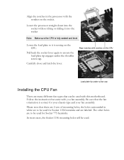
... that came with notches on the CPU. Follow the instruction that there are 2 sets of mounting holes, the holes surrounded in the processor with this motherboard. Lower the load plate so it into the socket without tilting or sliding it is correct for Socket 775 heatsinks. Pull back the socket lever...
... that came with notches on the CPU. Follow the instruction that there are 2 sets of mounting holes, the holes surrounded in the processor with this motherboard. Lower the load plate so it into the socket without tilting or sliding it is correct for Socket 775 heatsinks. Pull back the socket lever...
User Guide
Page 13
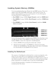
...to make all the connections prior to this step or to ensure normal operation. Determine if it would be at both sides of installing the motherboard into a system case depends on the memory DIMM to ensure the component is installed properly. 1. Unlock a DIMM slot by pressing the module ...: If using 2 DIMMs (Dual Channel), install into: DIMM slots 1 and 3. Four DIMMS: If using and if you are replacing an existing motherboard or working with an empty system case. This slot matches the slot on the chassis you are using 4 DIMMs (Dual Channel), install into the connector...
...to make all the connections prior to this step or to ensure normal operation. Determine if it would be at both sides of installing the motherboard into a system case depends on the memory DIMM to ensure the component is installed properly. 1. Unlock a DIMM slot by pressing the module ...: If using 2 DIMMs (Dual Channel), install into: DIMM slots 1 and 3. Four DIMMS: If using and if you are replacing an existing motherboard or working with an empty system case. This slot matches the slot on the chassis you are using 4 DIMMs (Dual Channel), install into the connector...
User Guide
Page 14
Before installing the motherboard, install the I/O shield from dust and foreign objects, and promotes correct airflow within the chassis. Press the I/O shield into place and make sure it fits securely. Installing the I/O Shield The motherboard kit comes with an I/O shield that is used to block radio frequency transmissions, protects internal components from the inside of the chassis.
Before installing the motherboard, install the I/O shield from dust and foreign objects, and promotes correct airflow within the chassis. Press the I/O shield into place and make sure it fits securely. Installing the I/O Shield The motherboard kit comes with an I/O shield that is used to block radio frequency transmissions, protects internal components from the inside of the chassis.
User Guide
Page 15
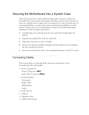
...screws. Align the mounting holes with a recommended minimum of a short circuit. Secure the motherboard with the stand offs. 3. This will include: Power Connections 24-pin ATX power (PW1) 8-pin ATX 12V power (PW12) Internal Headers Front panel IEEE 1394a USB Headers Audio &#...61553; Serial ATA II USB 2.0 Expansion slots CMOS Clear Button Securing the Motherboard into a System Case Most system ...
...screws. Align the mounting holes with a recommended minimum of a short circuit. Secure the motherboard with the stand offs. 3. This will include: Power Connections 24-pin ATX power (PW1) 8-pin ATX 12V power (PW12) Internal Headers Front panel IEEE 1394a USB Headers Audio &#...61553; Serial ATA II USB 2.0 Expansion slots CMOS Clear Button Securing the Motherboard into a System Case Most system ...
User Guide
Page 16
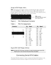
...(PW12) PW12, the 8-pin ATX 12V power connection, is the main power supply connector located along the edge of the board next to the DIMM slots. Make sure that the power supply cable and pins are properly aligned with the connector on the motherboard. These connectors support the thin ...Serial ATA II cables for 24-pin ATX Power (PW1) PW1 is used to connect the Serial ATA II device to the motherboard. PW1 Motherboard Connector Table 1. Firmly plug the power supply cable into ...
...(PW12) PW12, the 8-pin ATX 12V power connection, is the main power supply connector located along the edge of the board next to the DIMM slots. Make sure that the power supply cable and pins are properly aligned with the connector on the motherboard. These connectors support the thin ...Serial ATA II cables for 24-pin ATX Power (PW1) PW1 is used to connect the Serial ATA II device to the motherboard. PW1 Motherboard Connector Table 1. Firmly plug the power supply cable into ...
User Guide
Page 17
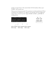
These connection points support RAID 0, RAID 1, and RAID 10 configurations. There are designed to be angled to 300MB/s data transfer rate. These connections are six (6) internal serial ATA connectors on this motherboard. The current Serial ATA II interface allows up to not interfere with any expansions cards. SATA 4 (bottom) SATA 2 (bottom) SATA 0 (bottom) SATA 5 (top) SATA 3 (top) SATA 1 (top) primary storage devices.
These connection points support RAID 0, RAID 1, and RAID 10 configurations. There are designed to be angled to 300MB/s data transfer rate. These connections are six (6) internal serial ATA connectors on this motherboard. The current Serial ATA II interface allows up to not interfere with any expansions cards. SATA 4 (bottom) SATA 2 (bottom) SATA 0 (bottom) SATA 5 (top) SATA 3 (top) SATA 1 (top) primary storage devices.
User Guide
Page 18
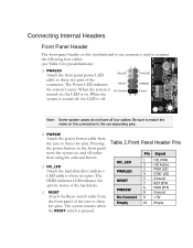
... do not have all four cables. The Power LED indicates the system's status. Connecting Internal Headers Front Panel Header The front panel header on this motherboard is off.
... do not have all four cables. The Power LED indicates the system's status. Connecting Internal Headers Front Panel Header The front panel header on this motherboard is off.
User Guide
Page 19
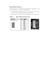
Connect the end of the system case (not all system cases are equipped with the front panel option). Table 3. IEEE1394a (Firewire) This motherboard has one IEEE 1394a onboard header. Alternatively, you can also connect this to the IEEE1394a header on the motherboard. Secure the bracket to either the front or rear panel of the cable to your system case (if applicable). 1. IEEE 1394a Connector Pins Connector IEEE 1394a Connector 10 9 8 7 6 5 4 3 2 1 Pin Signal 1 TPA+ 2 TPA- 3 GND 4 GND 5 TPB+ 6 TPB- 7 +12V 8 +12V 9 Empty 10 GND
Connect the end of the system case (not all system cases are equipped with the front panel option). Table 3. IEEE1394a (Firewire) This motherboard has one IEEE 1394a onboard header. Alternatively, you can also connect this to the IEEE1394a header on the motherboard. Secure the bracket to either the front or rear panel of the cable to your system case (if applicable). 1. IEEE 1394a Connector Pins Connector IEEE 1394a Connector 10 9 8 7 6 5 4 3 2 1 Pin Signal 1 TPA+ 2 TPA- 3 GND 4 GND 5 TPB+ 6 TPB- 7 +12V 8 +12V 9 Empty 10 GND
User Guide
Page 20
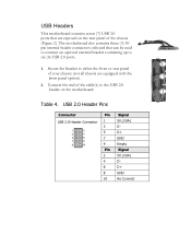
Table 4. Connect the end of the cable(s) to the USB 2.0 header on the rear panel of your chassis (not all chassis are exposed on the motherboard. USB 2.0 Header Pins Connector Pin USB 2.0 Header Connector 1 3 5 7 9 Pin 2 4 6 8 10 Signal 5V_DUAL DD+ GND Empty Signal ...5V_DUAL DD+ GND No Connect Secure the bracket to six (6) USB 2.0 ports. 1. USB Headers This motherboard contains seven (7) USB 2.0 ports that can be used to connect an optional external bracket containing up to either the front or rear panel of the...
Table 4. Connect the end of the cable(s) to the USB 2.0 header on the rear panel of your chassis (not all chassis are exposed on the motherboard. USB 2.0 Header Pins Connector Pin USB 2.0 Header Connector 1 3 5 7 9 Pin 2 4 6 8 10 Signal 5V_DUAL DD+ GND Empty Signal ...5V_DUAL DD+ GND No Connect Secure the bracket to six (6) USB 2.0 ports. 1. USB Headers This motherboard contains seven (7) USB 2.0 ports that can be used to connect an optional external bracket containing up to either the front or rear panel of the...
User Guide
Page 22
... a short across the pins. PCI Express x16/x8/x4 Slots These PCI Express slots are reserved for optimal performance. The design of this motherboard supports multiple Graphic Card technology. PCI Express x1 Slots There is one PCI Express x1 slot that is not seated properly, it is fully ...) for Graphic Cards and PCI Express x1 and x4 devices. Expansion Slots PCI Slots The PCI slot supports many expansion cards such as an EVGA Killer Xeno Network Card or Sound Card. Secure the card's metal bracket to the chassis back panel with PCI specifications. When installing a card...
... a short across the pins. PCI Express x16/x8/x4 Slots These PCI Express slots are reserved for optimal performance. The design of this motherboard supports multiple Graphic Card technology. PCI Express x1 Slots There is one PCI Express x1 slot that is not seated properly, it is fully ...) for Graphic Cards and PCI Express x1 and x4 devices. Expansion Slots PCI Slots The PCI slot supports many expansion cards such as an EVGA Killer Xeno Network Card or Sound Card. Secure the card's metal bracket to the chassis back panel with PCI specifications. When installing a card...
User Guide
Page 23
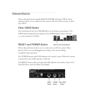
..., or clear the CMOS. The POWER button with an integrated LED indicates the activity status of the system during troubleshooting situations. Clear CMOS Button The motherboard uses the CMOS RAM to easily reset the system, turn on /off the system. The RESET button with LED indicates the system's status. RESET and...
..., or clear the CMOS. The POWER button with an integrated LED indicates the activity status of the system during troubleshooting situations. Clear CMOS Button The motherboard uses the CMOS RAM to easily reset the system, turn on /off the system. The RESET button with LED indicates the system's status. RESET and...
User Guide
Page 24
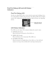
... booted into the Operating System. This Debug LED will remain on . Debug LED with CPU Temperature Monitor LED Status Indicators The LEDs near the 24pin ATX connector indicate the system's status. POWER LED (Green): When the System is powered on: This LED is on. DIMM LED (Orange): When the... is functional: This LED is on. STANDBY LED (Blue): When the System is in Standby Mode: This LED is on as long as the motherboard is useful during troubleshooting situations.
... booted into the Operating System. This Debug LED will remain on . Debug LED with CPU Temperature Monitor LED Status Indicators The LEDs near the 24pin ATX connector indicate the system's status. POWER LED (Green): When the System is powered on: This LED is on. DIMM LED (Orange): When the... is functional: This LED is on. STANDBY LED (Blue): When the System is in Standby Mode: This LED is on as long as the motherboard is useful during troubleshooting situations.