
User Guide
Page 1
User's Guide EVGA nForce 750i SLI Motherboard
User's Guide EVGA nForce 750i SLI Motherboard

User Guide
Page 4
... Contents User Guide ...i NVIDIA nForce 750i SLI Motherboard i Before You Begin...viii Parts NOT in the Kit viii Intentions of the Kit viii NVIDIA nForce 750i SLI Motherboard 1 Motherboard Specifications 1 Unpacking and Parts Descriptions 3 Unpacking ...3 Equipment ...3 NVIDIA nForce 750i SLI Motherboard 4 Hardware Installation 7 Safety Instructions...7 Preparing the Motherboard 8 Installing the CPU 8 Installing the CPU Fan 8 Installing Memory DIMMs 9 Installing the Motherboard 10 Installing the I/O Shield...
... Contents User Guide ...i NVIDIA nForce 750i SLI Motherboard i Before You Begin...viii Parts NOT in the Kit viii Intentions of the Kit viii NVIDIA nForce 750i SLI Motherboard 1 Motherboard Specifications 1 Unpacking and Parts Descriptions 3 Unpacking ...3 Equipment ...3 NVIDIA nForce 750i SLI Motherboard 4 Hardware Installation 7 Safety Instructions...7 Preparing the Motherboard 8 Installing the CPU 8 Installing the CPU Fan 8 Installing Memory DIMMs 9 Installing the Motherboard 10 Installing the I/O Shield...

User Guide
Page 7
Chassis Back Panel Connectors 6 Figure 3. Power Management Setup Menu 43 Figure 11. System Voltages Menu 57 EVGA vii PWR1 Motherboard Connector 13 Figure 5. CPU Feature Menu 34 Figure 9. PnP/PCI Configuration Menu 46 Figure 12. FSB & Memory Config Menu 53 Figure 15. Power Supply Connectors ... Setup Utility Main Menu 26 Figure 6. Integrated Peripherals Menu 39 Figure 10. Frequency/Voltage Control 51 Figure 14. Advanced BIOS Features Menu 33 Figure 8. NVIDIA nForce 750i SLI Motherboard Layout 5 Figure 2. PC Health Status 49 Figure 13.
Chassis Back Panel Connectors 6 Figure 3. Power Management Setup Menu 43 Figure 11. System Voltages Menu 57 EVGA vii PWR1 Motherboard Connector 13 Figure 5. CPU Feature Menu 34 Figure 9. PnP/PCI Configuration Menu 46 Figure 12. FSB & Memory Config Menu 53 Figure 15. Power Supply Connectors ... Setup Utility Main Menu 26 Figure 6. Integrated Peripherals Menu 39 Figure 10. Frequency/Voltage Control 51 Figure 14. Advanced BIOS Features Menu 33 Figure 8. NVIDIA nForce 750i SLI Motherboard Layout 5 Figure 2. PC Health Status 49 Figure 13.

User Guide
Page 8
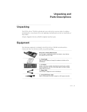
... system even though the current drives may already have purchased all necessary parts needed to make the motherboard functional. ‰ Intel microprocessor ‰ System Memory ‰ Cooling fan for proper system functionality. EVGA viii When replacing a motherboard in a PC case, it does not contain the following items that must be purchased separately to... provides you will use most of the cables provided in the Kit This kit contains all connecting cables necessary to install and connect your new EVGA nForce® 750i SLI motherboard.
... system even though the current drives may already have purchased all necessary parts needed to make the motherboard functional. ‰ Intel microprocessor ‰ System Memory ‰ Cooling fan for proper system functionality. EVGA viii When replacing a motherboard in a PC case, it does not contain the following items that must be purchased separately to... provides you will use most of the cables provided in the Kit This kit contains all connecting cables necessary to install and connect your new EVGA nForce® 750i SLI motherboard.

User Guide
Page 9
... 0, RAID 1, RAID 0+1, RAID 5, and JBOD ¾ Supports hot plug and NCQ (Native Command Queuing ) EVGA 1 EVGA nForce 750i SLI Motherboard Thank you get innovative NVIDIA SLI Technology for enhanced system performance. Supports up to 8 GBs of 12 inch x 9.6 inch ‰ Microprocessor support Intel... and Windows Vista 32bit/64bit ‰ Contains NVIDIA nForce 750i SLI MCP and SPP ‰ System Memory support Supports dual channel JEDEC DDR2-800. When combined with support for buying the EVGA nForce 750i SLI Motherboard: This motherboard offers the tools and performance PC users' demand.
... 0, RAID 1, RAID 0+1, RAID 5, and JBOD ¾ Supports hot plug and NCQ (Native Command Queuing ) EVGA 1 EVGA nForce 750i SLI Motherboard Thank you get innovative NVIDIA SLI Technology for enhanced system performance. Supports up to 8 GBs of 12 inch x 9.6 inch ‰ Microprocessor support Intel... and Windows Vista 32bit/64bit ‰ Contains NVIDIA nForce 750i SLI MCP and SPP ‰ System Memory support Supports dual channel JEDEC DDR2-800. When combined with support for buying the EVGA nForce 750i SLI Motherboard: This motherboard offers the tools and performance PC users' demand.
User Guide
Page 11
... Cable Allows a Molex power connector to adapt to a new chassis. All parts shipped in this kit are replacing a motherboard, you may vary between models, see product package) EVGA nForce 750i SLI Motherboard This PCI Express motherboard contains the NVIDIA nForce 750i SLI SPP and MCP and is included in the chassis to visually guide you are RoHS-compliant (lead-free...
... Cable Allows a Molex power connector to adapt to a new chassis. All parts shipped in this kit are replacing a motherboard, you may vary between models, see product package) EVGA nForce 750i SLI Motherboard This PCI Express motherboard contains the NVIDIA nForce 750i SLI SPP and MCP and is included in the chassis to visually guide you are RoHS-compliant (lead-free...

User Guide
Page 12
EVGA nForce 750i SLI Motherboard The EVGA nForce 750i SLI motherboard with compatible NVIDIA GeForce Graphics Cards. 1 - Driver Installation CD Contains drivers and software needed to the motherboard 1 - IDE-ATA 133 HDD Cable Passes data between the IDE connection on both the Motherboard and IDE device. 1 - 2-Way SLI Bridge Allows for a 2-Way SLI setup with the NVIDIA nForce 750i SLI SPP and MCP processor is a PCI Express, SLI-ready...
EVGA nForce 750i SLI Motherboard The EVGA nForce 750i SLI motherboard with compatible NVIDIA GeForce Graphics Cards. 1 - Driver Installation CD Contains drivers and software needed to the motherboard 1 - IDE-ATA 133 HDD Cable Passes data between the IDE connection on both the Motherboard and IDE device. 1 - 2-Way SLI Bridge Allows for a 2-Way SLI setup with the NVIDIA nForce 750i SLI SPP and MCP processor is a PCI Express, SLI-ready...

User Guide
Page 13
.... AUX Fan Connector 6. 24-pin ATX Power Connector 16. PCI Express x1 Slot 25. IDE Connector 3. Power Button 9. Serial Connector 21. PCI Slots 22. NVIDIA nForce 750i SLI Motherboard Layout EVGA 5 25 21 21 27 22 23 22 24 26 20 1 19 2 18 17 3 16 15 14 4 13 5 12 11 10 9 8 7 6 1. ... CPU Fan Connector 13. Backpanel Connectors (Figure 2) 26. 8-pin ATX_12V Power connector 27. PC Speaker Connector 7. Reset Button 10. USB Headers 4. Motherboard Battery 5. FDD Connector 17. Serial-ATA (SATA) Connectors 19. Diagnostic Code Display 2.
.... AUX Fan Connector 6. 24-pin ATX Power Connector 16. PCI Express x1 Slot 25. IDE Connector 3. Power Button 9. Serial Connector 21. PCI Slots 22. NVIDIA nForce 750i SLI Motherboard Layout EVGA 5 25 21 21 27 22 23 22 24 26 20 1 19 2 18 17 3 16 15 14 4 13 5 12 11 10 9 8 7 6 1. ... CPU Fan Connector 13. Backpanel Connectors (Figure 2) 26. 8-pin ATX_12V Power connector 27. PC Speaker Connector 7. Reset Button 10. USB Headers 4. Motherboard Battery 5. FDD Connector 17. Serial-ATA (SATA) Connectors 19. Diagnostic Code Display 2.
User Guide
Page 15
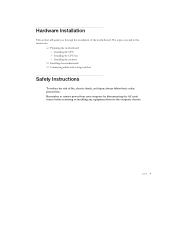
...; Installing the CPU ¾ Installing the CPU fan ¾ Installing the memory ‰ Installing the motherboard ‰ Connecting cables and setting switches Safety Instructions To reduce the risk of the motherboard. EVGA 7 Remember to remove power from your computer by disconnecting the AC main source before removing or installing any equipment from/to...
...; Installing the CPU ¾ Installing the CPU fan ¾ Installing the memory ‰ Installing the motherboard ‰ Connecting cables and setting switches Safety Instructions To reduce the risk of the motherboard. EVGA 7 Remember to remove power from your computer by disconnecting the AC main source before removing or installing any equipment from/to...

User Guide
Page 16
... fan assembly. Lift the load plate. It is no CPU installed. 3. Close the load plate over the CPU and press down while you hold it . 5. EVGA 8 There is a protective socket cover on the load plate to protect the socket when there is a good idea to save the cover so that the... fan orientation is fully seated and level in the processor with this motherboard. Remove the protective socket cover from the socket. 2. Align the notches in the socket. 7. Lower the processor straight down and away from the load plate...
... fan assembly. Lift the load plate. It is no CPU installed. 3. Close the load plate over the CPU and press down while you hold it . 5. EVGA 8 There is a protective socket cover on the load plate to protect the socket when there is a good idea to save the cover so that the... fan orientation is fully seated and level in the processor with this motherboard. Remove the protective socket cover from the socket. 2. Align the notches in the socket. 7. Lower the processor straight down and away from the load plate...
User Guide
Page 18
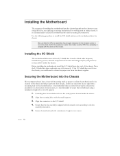
...spacers located inside of the chassis. Secure the motherboard with mounting studs or spacers to allow the mother board to be secured to the chassis and help to prevent short circuits. Be sure that stud to prevent the possibility of a short circuit. EVGA 10 Align the mounting holes with an I... /O shield into place and make sure the CPU Fan assembly is aligned with a mounting hole on the covers. Also make sure it is recommended to secure the motherboard using and if you are studs that...
...spacers located inside of the chassis. Secure the motherboard with mounting studs or spacers to allow the mother board to be secured to the chassis and help to prevent short circuits. Be sure that stud to prevent the possibility of a short circuit. EVGA 10 Align the mounting holes with an I... /O shield into place and make sure the CPU Fan assembly is aligned with a mounting hole on the covers. Also make sure it is recommended to secure the motherboard using and if you are studs that...
User Guide
Page 19
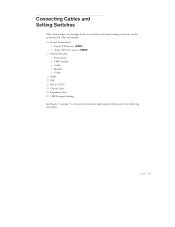
This will include: ‰ Power Connections ¾ 24-pin ATX power (PWR1) ¾ 8-pin ATX 12V power (PWR2) ‰ Internal Headers ¾ Front panel ¾ USB Headers ¾ Audio ¾ Speaker ¾ COM ‰ FDD ‰ IDE ‰ Serial ATA II ‰ Chassis Fans ‰ Expansion slots ‰ CMOS jumper settings See Figure 1 on the motherboard. EVGA 11 Connecting Cables and Setting Switches This section takes you through all the connections and switch settings necessary on page 5 to locate the connectors and jumpers referenced in the following procedure.
This will include: ‰ Power Connections ¾ 24-pin ATX power (PWR1) ¾ 8-pin ATX 12V power (PWR2) ‰ Internal Headers ¾ Front panel ¾ USB Headers ¾ Audio ¾ Speaker ¾ COM ‰ FDD ‰ IDE ‰ Serial ATA II ‰ Chassis Fans ‰ Expansion slots ‰ CMOS jumper settings See Figure 1 on the motherboard. EVGA 11 Connecting Cables and Setting Switches This section takes you through all the connections and switch settings necessary on page 5 to locate the connectors and jumpers referenced in the following procedure.
User Guide
Page 20
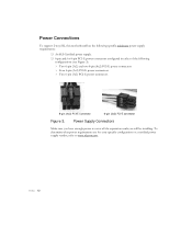
EVGA 12 Power Supply Connectors Make sure you will be installing. To determine what power requirements are for your specific configuration or a certified power supply vendor, refer to cover all the expansion cards you have enough power to www.slizone.com. Power Connections To support 2-way SLI, this motherboard... has the following specific minimum power supply requirements: ‰ An SLI-Certified power supply. ‰ 6-pin and/or 8-pin PCI-E power connectors configured ...
EVGA 12 Power Supply Connectors Make sure you will be installing. To determine what power requirements are for your specific configuration or a certified power supply vendor, refer to cover all the expansion cards you have enough power to www.slizone.com. Power Connections To support 2-way SLI, this motherboard... has the following specific minimum power supply requirements: ‰ An SLI-Certified power supply. ‰ 6-pin and/or 8-pin PCI-E power connectors configured ...
User Guide
Page 21
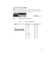
This connector is secure. Figure 4. Board edge PWR1 Motherboard Connector PWR1 connector Plug power cable from system power supply to the DIMM slots. PWR1 Pin Assignments Connector...15 GND 16 PS_ON 17 GND 18 GND 19 GND 20 RSVD 21 +5V 22 +5V 23 +5V 24 GND EVGA 13 Firmly plug the power supply cable into the connector and make sure it is notched, do not force in.... Make sure that the power supply cable and pins are properly aligned with the connector on the motherboard. 24-pin ATX Power (PWR1) PWR1 is the main power supply connector located along the edge of the board next...
This connector is secure. Figure 4. Board edge PWR1 Motherboard Connector PWR1 connector Plug power cable from system power supply to the DIMM slots. PWR1 Pin Assignments Connector...15 GND 16 PS_ON 17 GND 18 GND 19 GND 20 RSVD 21 +5V 22 +5V 23 +5V 24 GND EVGA 13 Firmly plug the power supply cable into the connector and make sure it is notched, do not force in.... Make sure that the power supply cable and pins are properly aligned with the connector on the motherboard. 24-pin ATX Power (PWR1) PWR1 is the main power supply connector located along the edge of the board next...
User Guide
Page 22
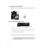
...rate between the drives may be reduced to the hard disk drive's documentation for the jumper settings. Connect the gray connector to the motherboard. 2. Connect the blue connector (the cable end with the two closely spaced black and gray connectors) to the connector and press firmly until ...seated. EVGA 14 Align the pins to the Ultra ATA master device. 3. Connect the black connector (the cable with a single connector) to a slave device. ...
...rate between the drives may be reduced to the hard disk drive's documentation for the jumper settings. Connect the gray connector to the motherboard. 2. Connect the blue connector (the cable end with the two closely spaced black and gray connectors) to the connector and press firmly until ...seated. EVGA 14 Align the pins to the Ultra ATA master device. 3. Connect the black connector (the cable with a single connector) to a slave device. ...
User Guide
Page 23
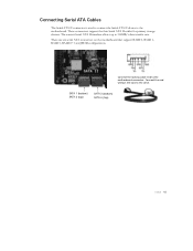
... the thin Serial ATA II cables for primary storage devices. Connect the locking cable end to the motherboard. SATA 1 (bottom) SATA 2 (top) SATA 3 (bottom) SATA 4 (top) EVGA 15 There are six serial ATA connectors on the motherboard that support RAID 0, RAID 1, RAID 5, RAID 0+1 and JBOD configurations. Connecting Serial ATA Cables The Serial ATA...
... the thin Serial ATA II cables for primary storage devices. Connect the locking cable end to the motherboard. SATA 1 (bottom) SATA 2 (top) SATA 3 (bottom) SATA 4 (top) EVGA 15 There are six serial ATA connectors on the motherboard that support RAID 0, RAID 1, RAID 5, RAID 0+1 and JBOD configurations. Connecting Serial ATA Cables The Serial ATA...
User Guide
Page 24
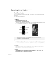
...pins. ‰ PWRSW Attach the power button cable from the front panel of the connector. The system restarts when the RESET switch is pressed. EVGA 16 Some chassis do not have all four cables. The HDD indicator LED indicates the activity status of the hard disk drives. ‰ RESET ... the case to these two pins. The Power LED indicates the system's status. Connecting Internal Headers Front Panel Header The front panel header on this motherboard is one connector used to connect the following four cables: (see Table 2 for pin definitions) ‰ PWRLED Attach the front panel power LED ...
...pins. ‰ PWRSW Attach the power button cable from the front panel of the connector. The system restarts when the RESET switch is pressed. EVGA 16 Some chassis do not have all four cables. The HDD indicator LED indicates the activity status of the hard disk drives. ‰ RESET ... the case to these two pins. The Power LED indicates the system's status. Connecting Internal Headers Front Panel Header The front panel header on this motherboard is one connector used to connect the following four cables: (see Table 2 for pin definitions) ‰ PWRLED Attach the front panel power LED ...
User Guide
Page 25
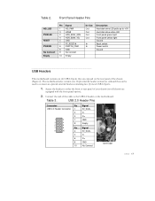
...drive active LED Front panel green light Front panel yellow light Ground Reset switch Power switch Ground USB Headers This motherboard contains six (6) USB 2.0 ports that are equipped with the front panel option). 2. Secure the bracket to ...the USB 2.0 header on the rear panel of your chassis (not all chassis are exposed on the motherboard. Connect the end of the cable to either the front or rear panel of the chassis (Figure 2). Front... 3 5 7 9 Pin 2 4 6 8 10 Signal 5V_DUAL DD+ GND Empty Signal 5V_DUAL DD+ GND No Connect Card Edge EVGA 17 Table 3. Table 2.
...drive active LED Front panel green light Front panel yellow light Ground Reset switch Power switch Ground USB Headers This motherboard contains six (6) USB 2.0 ports that are equipped with the front panel option). 2. Secure the bracket to ...the USB 2.0 header on the rear panel of your chassis (not all chassis are exposed on the motherboard. Connect the end of the cable to either the front or rear panel of the chassis (Figure 2). Front... 3 5 7 9 Pin 2 4 6 8 10 Signal 5V_DUAL DD+ GND Empty Signal 5V_DUAL DD+ GND No Connect Card Edge EVGA 17 Table 3. Table 2.

User Guide
Page 27
.... CPU Fan Connector 4 3 2 GND SENSE PWR CONTROL 3 2 Auxiliary Fan Connector GND +12V SENSE EVGA nForce 750i SLI SPP/MCP Fan Connector 3 2 Install the fan over the nForce 750i SLI SPP to pins 1, 2, and 3 on the motherboard. The fan plugs into a 3-pin connector. The fan speed can be detected and viewed in the PC Health Status section of the...
.... CPU Fan Connector 4 3 2 GND SENSE PWR CONTROL 3 2 Auxiliary Fan Connector GND +12V SENSE EVGA nForce 750i SLI SPP/MCP Fan Connector 3 2 Install the fan over the nForce 750i SLI SPP to pins 1, 2, and 3 on the motherboard. The fan plugs into a 3-pin connector. The fan speed can be detected and viewed in the PC Health Status section of the...
User Guide
Page 28
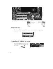
Floppy Disk Drive (FDD) Connector The motherboard supports a standard 360K, 720K, 1.2M, 1.44m, and a 2.88M floppy disk drive (FDD). Serial Connector 3 2 GND +12V SENSE Auxiliary Fan Connector MCP Fan Connector 3 2 GND +12V SENSE The motherboard kit provides an additional serial connector head for your system. EVGA 20 Connect one side of a switching cable to the header and then attach the serial device to the other side of the cable.
Floppy Disk Drive (FDD) Connector The motherboard supports a standard 360K, 720K, 1.2M, 1.44m, and a 2.88M floppy disk drive (FDD). Serial Connector 3 2 GND +12V SENSE Auxiliary Fan Connector MCP Fan Connector 3 2 GND +12V SENSE The motherboard kit provides an additional serial connector head for your system. EVGA 20 Connect one side of a switching cable to the header and then attach the serial device to the other side of the cable.
