
User Guide
Page 4
... NVIDIA nForce 750i SLI Motherboard 1 Motherboard Specifications 1 Unpacking and Parts Descriptions 3 Unpacking ...3 Equipment ...3 NVIDIA nForce 750i SLI Motherboard 4 Hardware Installation 7 Safety Instructions...7 Preparing the Motherboard 8 Installing the CPU 8 Installing the CPU Fan 8 Installing Memory DIMMs 9 Installing the Motherboard 10 Installing the I/O Shield 10 Securing the Motherboard into the Chassis 10 Connecting Cables and Setting Switches 11 Power Connections 12 24-pin ATX Power...
... NVIDIA nForce 750i SLI Motherboard 1 Motherboard Specifications 1 Unpacking and Parts Descriptions 3 Unpacking ...3 Equipment ...3 NVIDIA nForce 750i SLI Motherboard 4 Hardware Installation 7 Safety Instructions...7 Preparing the Motherboard 8 Installing the CPU 8 Installing the CPU Fan 8 Installing Memory DIMMs 9 Installing the Motherboard 10 Installing the I/O Shield 10 Securing the Motherboard into the Chassis 10 Connecting Cables and Setting Switches 11 Power Connections 12 24-pin ATX Power...

User Guide
Page 9
.../64bit ‰ Contains NVIDIA nForce 750i SLI MCP and SPP ‰ System Memory support Supports dual channel JEDEC DDR2-800. EVGA nForce 750i SLI Motherboard Thank you get innovative NVIDIA SLI Technology for enhanced system performance. Motherboard Specifications ‰ Size ATX form factor of DDR2 memory.... ¾ Four Serial ATA II connectors ¾ NVIDIA Media Shield RAID with two SLI-Ready NVIDIA GeForce graphics cards, you for buying the EVGA nForce 750i SLI Motherboard: This motherboard offers the tools and performance PC users' demand. When combined with support for RAID ...
.../64bit ‰ Contains NVIDIA nForce 750i SLI MCP and SPP ‰ System Memory support Supports dual channel JEDEC DDR2-800. EVGA nForce 750i SLI Motherboard Thank you get innovative NVIDIA SLI Technology for enhanced system performance. Motherboard Specifications ‰ Size ATX form factor of DDR2 memory.... ¾ Four Serial ATA II connectors ¾ NVIDIA Media Shield RAID with two SLI-Ready NVIDIA GeForce graphics cards, you for buying the EVGA nForce 750i SLI Motherboard: This motherboard offers the tools and performance PC users' demand. When combined with support for RAID ...

User Guide
Page 13
... 27. Clear CMOS Button 8. Serial-ATA (SATA) Connectors 19. Front panel Audio Connector 24. IDE Connector 3. NVIDIA nForce 750i SLI Motherboard Layout EVGA 5 CPU Fan Connector 13. Diagnostic Code Display 2. AUX Fan Connector 6. 24-pin ATX Power Connector 16. Motherboard Battery 5. Power Button 9. Reset Button 10. Front Panel Connector 20. System Memory (DIMM) Slots for DDR2 15...
... 27. Clear CMOS Button 8. Serial-ATA (SATA) Connectors 19. Front panel Audio Connector 24. IDE Connector 3. NVIDIA nForce 750i SLI Motherboard Layout EVGA 5 CPU Fan Connector 13. Diagnostic Code Display 2. AUX Fan Connector 6. 24-pin ATX Power Connector 16. Motherboard Battery 5. Power Button 9. Reset Button 10. Front Panel Connector 20. System Memory (DIMM) Slots for DDR2 15...
User Guide
Page 19
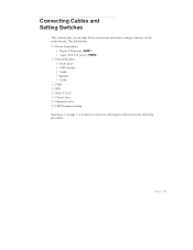
Connecting Cables and Setting Switches This section takes you through all the connections and switch settings necessary on page 5 to locate the connectors and jumpers referenced in the following procedure. EVGA 11 This will include: ‰ Power Connections ¾ 24-pin ATX power (PWR1) ¾ 8-pin ATX 12V power (PWR2) ‰ Internal Headers ¾ Front panel ¾ USB Headers ¾ Audio ¾ Speaker ¾ COM ‰ FDD ‰ IDE ‰ Serial ATA II ‰ Chassis Fans ‰ Expansion slots ‰ CMOS jumper settings See Figure 1 on the motherboard.
Connecting Cables and Setting Switches This section takes you through all the connections and switch settings necessary on page 5 to locate the connectors and jumpers referenced in the following procedure. EVGA 11 This will include: ‰ Power Connections ¾ 24-pin ATX power (PWR1) ¾ 8-pin ATX 12V power (PWR2) ‰ Internal Headers ¾ Front panel ¾ USB Headers ¾ Audio ¾ Speaker ¾ COM ‰ FDD ‰ IDE ‰ Serial ATA II ‰ Chassis Fans ‰ Expansion slots ‰ CMOS jumper settings See Figure 1 on the motherboard.
User Guide
Page 21
Make sure that the power supply cable and pins are properly aligned with the connector on the motherboard. This connector is secure. PWR1 Pin Assignments Connector 24 12 Pin Signal 1 +3.3V 2 ... 19 GND 20 RSVD 21 +5V 22 +5V 23 +5V 24 GND EVGA 13 Board edge PWR1 Motherboard Connector PWR1 connector Plug power cable from system power supply to the DIMM slots.... Figure 4. Firmly plug the power supply cable into the connector and make sure it is notched, do not force in. 24-pin ATX...
Make sure that the power supply cable and pins are properly aligned with the connector on the motherboard. This connector is secure. PWR1 Pin Assignments Connector 24 12 Pin Signal 1 +3.3V 2 ... 19 GND 20 RSVD 21 +5V 22 +5V 23 +5V 24 GND EVGA 13 Board edge PWR1 Motherboard Connector PWR1 connector Plug power cable from system power supply to the DIMM slots.... Figure 4. Firmly plug the power supply cable into the connector and make sure it is notched, do not force in. 24-pin ATX...
User Guide
Page 22
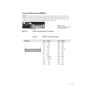
...protocol are attached to the same cable, the maximum transfer rate between the drives may be reduced to the connector and press firmly until seated. EVGA 14 If you install two hard disk drives, you must configure the second drive as a slave device by setting its jumper accordingly. This ... Power (PWR2) PWR2, the 8-pin ATX 12V power connection, is notched, do not force in. Connect the blue connector (the cable end with the two closely spaced black and gray connectors) to the motherboard. 2. GND 14 58 12V Connecting IDE Hard Disk Drives IDE Connector Card Edge The IDE connector ...
...protocol are attached to the same cable, the maximum transfer rate between the drives may be reduced to the connector and press firmly until seated. EVGA 14 If you install two hard disk drives, you must configure the second drive as a slave device by setting its jumper accordingly. This ... Power (PWR2) PWR2, the 8-pin ATX 12V power connection, is notched, do not force in. Connect the blue connector (the cable end with the two closely spaced black and gray connectors) to the motherboard. 2. GND 14 58 12V Connecting IDE Hard Disk Drives IDE Connector Card Edge The IDE connector ...

Visual Guide
Page 1
... an ESD wrist strap or anti-static mat when handling computer components. EVGA nForce 750i SLITM Visual Guide 1 a. Plug in one of system memory (DIMM) in the OFF position then connect your 24-Pin ATX Power Connector and 8-Pin CPU Power Connector to the DIMM slot of ... SATA Connectors or to both the graphics card and the hard disk drive. b. The following procedures. d. b. b. c. b. It is in to the motherboard. 8 a. c. LEDs will vary depending on the graphic card bus type. For example: wood, cardboard box, or an anti-static mat. 2 a. ...
... an ESD wrist strap or anti-static mat when handling computer components. EVGA nForce 750i SLITM Visual Guide 1 a. Plug in one of system memory (DIMM) in the OFF position then connect your 24-Pin ATX Power Connector and 8-Pin CPU Power Connector to the DIMM slot of ... SATA Connectors or to both the graphics card and the hard disk drive. b. The following procedures. d. b. b. c. b. It is in to the motherboard. 8 a. c. LEDs will vary depending on the graphic card bus type. For example: wood, cardboard box, or an anti-static mat. 2 a. ...

Visual Guide
Page 2
...when there is needed whenever transporting or shipping the motherboard.) 4. Lower the CPU straight into the socket. This motherboard supports up to all products. It is highly..., floppy drive, and DVD-ROM drives to four 240-pin DDR2 memory modules. EVGA nForce 750i SLITM Quick Install Guide Gaming ● Imaging ● 3D Video ● Entertainment...GROUND 6 GROUND Connector Speaker Header 1 2 3 4 Pin Signal 1 VCC 2 Empty 3 GND 4 Speaker 24 pin ATX power IDE Channel SATA ports Blank 10 9 No Connect PWRSW RESET PWRLED + Floppy Channel 21 HD_LED + Connector Pin ...
...when there is needed whenever transporting or shipping the motherboard.) 4. Lower the CPU straight into the socket. This motherboard supports up to all products. It is highly..., floppy drive, and DVD-ROM drives to four 240-pin DDR2 memory modules. EVGA nForce 750i SLITM Quick Install Guide Gaming ● Imaging ● 3D Video ● Entertainment...GROUND 6 GROUND Connector Speaker Header 1 2 3 4 Pin Signal 1 VCC 2 Empty 3 GND 4 Speaker 24 pin ATX power IDE Channel SATA ports Blank 10 9 No Connect PWRSW RESET PWRLED + Floppy Channel 21 HD_LED + Connector Pin ...