
User Guide
Page 3
... P55 Micro Motherboard...1 Before You Begin...7 Before You Begin...7 Parts NOT in the Kit ...7 EVGA P55 Micro Motherboard ...8 Motherboard Specifications...8 Hardware Installation ...10 Safety Instructions ...10 Preparing the Motherboard ...11 Installing the CPU ...11 Installing the CPU Fan ...12 Installing System Memory (DIMMs) ...13 Installing the Motherboard...13 Installing the I/O Shield ...14 Securing the Motherboard into a System Case ...15 Connecting Cables ...15 24-pin ATX Power (PW1) ...16 8-pin ATX 12V Power (PW12) ...16 Connecting Serial ATA Cables...16 Connecting Internal Headers...
... P55 Micro Motherboard...1 Before You Begin...7 Before You Begin...7 Parts NOT in the Kit ...7 EVGA P55 Micro Motherboard ...8 Motherboard Specifications...8 Hardware Installation ...10 Safety Instructions ...10 Preparing the Motherboard ...11 Installing the CPU ...11 Installing the CPU Fan ...12 Installing System Memory (DIMMs) ...13 Installing the Motherboard...13 Installing the I/O Shield ...14 Securing the Motherboard into a System Case ...15 Connecting Cables ...15 24-pin ATX Power (PW1) ...16 8-pin ATX 12V Power (PW12) ...16 Connecting Serial ATA Cables...16 Connecting Internal Headers...
User Guide
Page 5
...40 EVGA P55 Micro Motherboard Allocate IRQ to PCI VGA ...34 Palette Snooping ...34 PCI IDE BusMaster ...34 OffBoard PCI/ISA IDE Card ...34 IRQ Settings ...34 Boot Configuration Features ...35 Boot Device Priority ...35 Hard Disk Drives ...35 CD/DVD Drives ...36 Power Management Features ...36 ACPI Configuration ...36 SLP_S4# Min. Assertion Width ...36 Restore on AC Power Loss ...37 Hardware Health Configure...37 H/W Health Function ...37 CPU Fan Mode Setting ...38 Frequency/Voltage Control Menu ...38 Memory Configure ...38 CPU Configuration ...38 Installing Drivers and Software ...39 Windows...
...40 EVGA P55 Micro Motherboard Allocate IRQ to PCI VGA ...34 Palette Snooping ...34 PCI IDE BusMaster ...34 OffBoard PCI/ISA IDE Card ...34 IRQ Settings ...34 Boot Configuration Features ...35 Boot Device Priority ...35 Hard Disk Drives ...35 CD/DVD Drives ...36 Power Management Features ...36 ACPI Configuration ...36 SLP_S4# Min. Assertion Width ...36 Restore on AC Power Loss ...37 Hardware Health Configure...37 H/W Health Function ...37 CPU Fan Mode Setting ...38 Frequency/Voltage Control Menu ...38 Memory Configure ...38 CPU Configuration ...38 Installing Drivers and Software ...39 Windows...

User Guide
Page 6
Figure 9. Figure 10. Figure 7. Figure 3. List of Figures Figure 1. Figure 5. Figure 6. Figure 2. Figure 8. PW1 Motherboard Connector ...16 CMOS Setup Utility Main Menu ...27 Standard BIOS Features Menu ...28 Advanced BIOS Features ...30 Advanced Chipset Features ...31 PCI/PNP Resource Management ...33 Boot Configuration Features ...35 Power Management Features ...36 Hardware Health Configure ...37 Frequency/Voltage Control ...38 Figure 4.
Figure 9. Figure 10. Figure 7. Figure 3. List of Figures Figure 1. Figure 5. Figure 6. Figure 2. Figure 8. PW1 Motherboard Connector ...16 CMOS Setup Utility Main Menu ...27 Standard BIOS Features Menu ...28 Advanced BIOS Features ...30 Advanced Chipset Features ...31 PCI/PNP Resource Management ...33 Boot Configuration Features ...35 Power Management Features ...36 Hardware Health Configure ...37 Frequency/Voltage Control ...38 Figure 4.
User Guide
Page 7
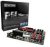
....evga.com/support/motherboard/. Intel Socket 1156 Processor DDR3 System Memory Socket 1156 or Socket 775 Cooling fan PCI Express or PCI Graphics Card Power Supply EVGA assumes you will need to install and connect your new EVGA P55 Micro Motherboard. When replacing a motherboard in the Kit This kit contains all the hardware necessary to reinstall an operating system even though the current hard disk may already have purchased all the necessary parts needed to make the motherboard functional. EVGA P55 Micro Motherboard...
....evga.com/support/motherboard/. Intel Socket 1156 Processor DDR3 System Memory Socket 1156 or Socket 775 Cooling fan PCI Express or PCI Graphics Card Power Supply EVGA assumes you will need to install and connect your new EVGA P55 Micro Motherboard. When replacing a motherboard in the Kit This kit contains all the hardware necessary to reinstall an operating system even though the current hard disk may already have purchased all the necessary parts needed to make the motherboard functional. EVGA P55 Micro Motherboard...
User Guide
Page 8
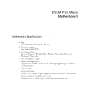
... 16GBs of 9.6 inch x 9.6 inch Processor support Intel Socket 1156 CPU's Operating systems: Supports Windows XP 32bit/64bit, Windows Vista 32bit/64bit, and Windows 7 32bit/64bit Intel P55 Express Chipset System Memory support Supports dual channel DDR3-1600+. EVGA P55 Micro Motherboard Motherboard Specifications Size ATX form factor of DDR3 memory. USB 2.0 Ports Supports hot plug Twelve USB 2.0 ports (Eight rear panel ports, four onboard USB headers) Supports wake-up from S1 and S3 mode Supports USB 2.0 protocol up to a 480 Mbps...
... 16GBs of 9.6 inch x 9.6 inch Processor support Intel Socket 1156 CPU's Operating systems: Supports Windows XP 32bit/64bit, Windows Vista 32bit/64bit, and Windows 7 32bit/64bit Intel P55 Express Chipset System Memory support Supports dual channel DDR3-1600+. EVGA P55 Micro Motherboard Motherboard Specifications Size ATX form factor of DDR3 memory. USB 2.0 Ports Supports hot plug Twelve USB 2.0 ports (Eight rear panel ports, four onboard USB headers) Supports wake-up from S1 and S3 mode Supports USB 2.0 protocol up to a 480 Mbps...

User Guide
Page 15
...; Power Connections 24-pin ATX power (PW1) 8-pin ATX 12V power (PW12) Internal Headers Front panel IEEE 1394a USB Headers Audio Serial ATA II USB 2.0 Expansion slots CMOS Clear Button Align the connectors to prevent short circuits. If there are studs that do not align with the chassis vents according to the fan assembly instruction. Ensure that the fan assembly is aligned with a mounting hole on the motherboard, it is recommended that stud to secure the motherboard using...
...; Power Connections 24-pin ATX power (PW1) 8-pin ATX 12V power (PW12) Internal Headers Front panel IEEE 1394a USB Headers Audio Serial ATA II USB 2.0 Expansion slots CMOS Clear Button Align the connectors to prevent short circuits. If there are studs that do not align with the chassis vents according to the fan assembly instruction. Ensure that the fan assembly is aligned with a mounting hole on the motherboard, it is recommended that stud to secure the motherboard using...

User Guide
Page 16
... main power supply connector located along the edge of the board next to the motherboard. These connectors support the thin Serial ATA II cables for PW1 PW1 connector Plug power cable from system power supply to the connector and press firmly until seated. Connecting Serial ATA Cables The Serial ATA II connector is used to connect the Serial ATA II device to the DIMM slots. Make sure that the power supply cable and pins are properly aligned with the connector on the motherboard. 24-pin ATX Power...
... main power supply connector located along the edge of the board next to the motherboard. These connectors support the thin Serial ATA II cables for PW1 PW1 connector Plug power cable from system power supply to the connector and press firmly until seated. Connecting Serial ATA Cables The Serial ATA II connector is used to connect the Serial ATA II device to the DIMM slots. Make sure that the power supply cable and pins are properly aligned with the connector on the motherboard. 24-pin ATX Power...

User Guide
Page 18
... is turned off, the LED is one connector used to connect the following four cables. (see Table 2 for pin definitions): PWRLED Attach the front panel power LED cable to these two pins. Attach the hard disk drive indicator LED cable to these two pins. Connecting Internal Headers Front Panel Header The front panel header on this motherboard is off. The HDD indicator LED indicates the activity status of the case to the corresponding pins. PWRSW Attach the power button cable from...
... is turned off, the LED is one connector used to connect the following four cables. (see Table 2 for pin definitions): PWRLED Attach the front panel power LED cable to these two pins. Attach the hard disk drive indicator LED cable to these two pins. Connecting Internal Headers Front Panel Header The front panel header on this motherboard is off. The HDD indicator LED indicates the activity status of the case to the corresponding pins. PWRSW Attach the power button cable from...

User Guide
Page 22
... design of this motherboard supports multiple Graphic Card technology. Secure the card's metal bracket to the chassis back panel with the screw used to hold the blank cover. When installing a PCI Express Graphic Card, be sure that comply with PCI specifications. PCI Express x16/x8/x4 Slots These PCI Express slots are reserved for Graphic Cards and PCI Express x1 and x4 devices. Expansion Slots PCI Slots The PCI slot supports many expansion cards such as an EVGA Killer Xeno Network Card or Sound Card. The x1 slot provides 250...
... design of this motherboard supports multiple Graphic Card technology. Secure the card's metal bracket to the chassis back panel with the screw used to hold the blank cover. When installing a PCI Express Graphic Card, be sure that comply with PCI specifications. PCI Express x16/x8/x4 Slots These PCI Express slots are reserved for Graphic Cards and PCI Express x1 and x4 devices. Expansion Slots PCI Slots The PCI slot supports many expansion cards such as an EVGA Killer Xeno Network Card or Sound Card. The x1 slot provides 250...

User Guide
Page 26
... screen during the Power On Self Test (POST). Enter BIOS Setup The BIOS is critical to maintain optimal system performance and stability. Main Menu The main menu allows you choose. Power on the computer. CMOS Setup Utility - Copyright (C) 1985-2005, American Megatrends Standard BIOS Features Advanced BIOS Features Advanced Chipset Features PCI/PNP Resource Management Boot Configuration Features Power Management Features Hardware Health Configure Frequency/Voltage Control Load Optimal Defaults...
... screen during the Power On Self Test (POST). Enter BIOS Setup The BIOS is critical to maintain optimal system performance and stability. Main Menu The main menu allows you choose. Power on the computer. CMOS Setup Utility - Copyright (C) 1985-2005, American Megatrends Standard BIOS Features Advanced BIOS Features Advanced Chipset Features PCI/PNP Resource Management Boot Configuration Features Power Management Features Hardware Health Configure Frequency/Voltage Control Load Optimal Defaults...

User Guide
Page 30
... Settings Configuration Use this to configure your storage drivers and to malfunction IDE Configuration [Press Boot Settings Configuration[Press AHCI Configuration [Press USB Configuration [Press Enter] Enter] Enter] Enter] Help Item Main Level Select Removable Boot Device Priority Move Enter:Select F5:Previous Values +/-/:Value F10:Save ESC:Exit F1:General Help F7:Optimized Defaults Figure 4. AHCI Configuration This menu will allow you to configure various system options, such as S.M.A.R.T. Advanced BIOS Features IDE Configuration Use this option to change...
... Settings Configuration Use this to configure your storage drivers and to malfunction IDE Configuration [Press Boot Settings Configuration[Press AHCI Configuration [Press USB Configuration [Press Enter] Enter] Enter] Enter] Help Item Main Level Select Removable Boot Device Priority Move Enter:Select F5:Previous Values +/-/:Value F10:Save ESC:Exit F1:General Help F7:Optimized Defaults Figure 4. AHCI Configuration This menu will allow you to configure various system options, such as S.M.A.R.T. Advanced BIOS Features IDE Configuration Use this option to change...

User Guide
Page 31
...enable Legacy USB support, force USB 1.1 mode and more . Advanced Chipset Settings _____ WARNING: Setting wrong values in below sections may cause system to change the settings. Configuring the BIOS USB Configuration This option menu allows you to set the primary graphics adapter, and more . Advanced Chipset Features Select Advanced Chipset Features from the CMOS Setup Utility menu and press Enter to malfunction. North Bridge Configuration [Press Enter] PCI Express Configuration [Press Enter] Intel VT-d [Disabled] HD Audio Controller [Enabled] IEEE1394 [Enabled...
...enable Legacy USB support, force USB 1.1 mode and more . Advanced Chipset Settings _____ WARNING: Setting wrong values in below sections may cause system to change the settings. Configuring the BIOS USB Configuration This option menu allows you to set the primary graphics adapter, and more . Advanced Chipset Features Select Advanced Chipset Features from the CMOS Setup Utility menu and press Enter to malfunction. North Bridge Configuration [Press Enter] PCI Express Configuration [Press Enter] Intel VT-d [Disabled] HD Audio Controller [Enabled] IEEE1394 [Enabled...
User Guide
Page 32
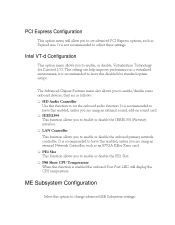
... option menu allows you to set advanced PCI Express options, such as follows: HD Audio Controller Use this enabled, unless you are using an external sound, add-on sound card. IEEE1394 This function allows you to enable or disable the IEEE1394 (Firewire) interface. LAN Controller This function allows you to adjust these settings. It is enabled the onboard Post Port LED will allow you to enable or disable the PE1 Slot. PCI Express Configuration This option menu will display the CPU temperature...
... option menu allows you to set advanced PCI Express options, such as follows: HD Audio Controller Use this enabled, unless you are using an external sound, add-on sound card. IEEE1394 This function allows you to enable or disable the IEEE1394 (Firewire) interface. LAN Controller This function allows you to adjust these settings. It is enabled the onboard Post Port LED will allow you to enable or disable the PE1 Slot. PCI Express Configuration This option menu will display the CPU temperature...

User Guide
Page 33
... Resource Management from the CMOS Setup Utility menu and press Enter to PCI VGA Palette Snooping PCI IDE BusMaster OffBoard PCI/ISA IDE Card IRQ3 IRQ4 IRQ5 IRQ7 IRQ9 IRQ10 Move Enter:Select F5:Previous Values [No] [No] [64] [Yes] [Disabled] [Enabled] [Auto] [Available] [Available] [Available] [Available] [Available] [Available] +/-/:Value F10:Save Help Item Clear NVRAM during System Boot. Clear NVRAM Plug & Play O/S PCI Latency Timer Allocate IRQ to display the advanced...
... Resource Management from the CMOS Setup Utility menu and press Enter to PCI VGA Palette Snooping PCI IDE BusMaster OffBoard PCI/ISA IDE Card IRQ3 IRQ4 IRQ5 IRQ7 IRQ9 IRQ10 Move Enter:Select F5:Previous Values [No] [No] [64] [Yes] [Disabled] [Enabled] [Auto] [Available] [Available] [Available] [Available] [Available] [Available] +/-/:Value F10:Save Help Item Clear NVRAM during System Boot. Clear NVRAM Plug & Play O/S PCI Latency Timer Allocate IRQ to display the advanced...

User Guide
Page 35
... F6:Fail-Safe Defaults F7:Optimized Defaults Figure 7. Boot Configuration Features Boot Device Priority This option menu will allow specification of the Hard Disk boot priority sequence. Hard Disk Drives This option menu allows you specification of the boot device priority sequence. Boot Configuration Features Select Boot Configuration Features from the CMOS Setup Utility menu and press Enter to display the settings. Boot Device Priority Hard Disk Drives CD/DVD Drives [Press Enter] [Press Enter] [Press Enter] Help Item Specifies the Boot Device Priority...
... F6:Fail-Safe Defaults F7:Optimized Defaults Figure 7. Boot Configuration Features Boot Device Priority This option menu will allow specification of the Hard Disk boot priority sequence. Hard Disk Drives This option menu allows you specification of the boot device priority sequence. Boot Configuration Features Select Boot Configuration Features from the CMOS Setup Utility menu and press Enter to display the settings. Boot Device Priority Hard Disk Drives CD/DVD Drives [Press Enter] [Press Enter] [Press Enter] Help Item Specifies the Boot Device Priority...

User Guide
Page 36
... ACPI configurations. Assertion Width [4 to display the settings. SLP_S4# Min. Move Enter:Select +/-/:Value F10:Save ESC:Exit F1:General Help F5:Previous Values F7:Optimized Defaults Move Enter:Select +/-/PU/PD:Value F10:Save ESC:Exit F1:General Help F5:Previous Values F6:Fail-Safe Defaults F7:Optimized Defaults Figure 8. CD/DVD Drives This option menu allows you specification of the CD/DVD boot priority sequence. Power...
... ACPI configurations. Assertion Width [4 to display the settings. SLP_S4# Min. Move Enter:Select +/-/:Value F10:Save ESC:Exit F1:General Help F5:Previous Values F7:Optimized Defaults Move Enter:Select +/-/PU/PD:Value F10:Save ESC:Exit F1:General Help F5:Previous Values F6:Fail-Safe Defaults F7:Optimized Defaults Figure 8. CD/DVD Drives This option menu allows you specification of the CD/DVD boot priority sequence. Power...

User Guide
Page 37
... Health Monitoring. Configuring the BIOS Restore on AC Power Loss This menu allows adjustment of the AC Power Loss parameters. Hardware Health Configure H/W Health Function [Enabled] _____ CPU Temperature Sensor VREG Temperature Sensor System Temperature Sensor CPU Fan Speed Power Fan Speed Chassis Fan Speed VCore Memory CPU VTT PCH +5V :34C/93F :48C/118F :34C/93F :3264 RPM :1337 RPM :3864 RPM :1.337 :1.481 :1.021 :1.031 :4.961 V V V V V Help Item Enables Hardware Health Monitoring Device. Move Enter...
... Health Monitoring. Configuring the BIOS Restore on AC Power Loss This menu allows adjustment of the AC Power Loss parameters. Hardware Health Configure H/W Health Function [Enabled] _____ CPU Temperature Sensor VREG Temperature Sensor System Temperature Sensor CPU Fan Speed Power Fan Speed Chassis Fan Speed VCore Memory CPU VTT PCH +5V :34C/93F :48C/118F :34C/93F :3264 RPM :1337 RPM :3864 RPM :1.337 :1.481 :1.021 :1.031 :4.961 V V V V V Help Item Enables Hardware Health Monitoring Device. Move Enter...

User Guide
Page 38
... CPU PLL [Auto] DIMM 1/2 DQ Vref [ 849 KHz Move Enter:Select +/-/PU/PD:Value F10:Save ESC:Exit F1:General Help F5:Previous Values F6:Fail-Safe Defaults F7:Optimized Defaults Figure 10. CPU Configuration This menu will allow the configuration of the fan mode configuration. Frequency/Voltage Control Menu Select Frequency/Voltage Control from the CMOS Setup Utility menu and press Enter to display the settings. CPU Fan Mode Setting This function allows change of advanced CPU settings, such as Virtualization Technology, CPU SpeedStep, or CPU power saving options...
... CPU PLL [Auto] DIMM 1/2 DQ Vref [ 849 KHz Move Enter:Select +/-/PU/PD:Value F10:Save ESC:Exit F1:General Help F5:Previous Values F6:Fail-Safe Defaults F7:Optimized Defaults Figure 10. CPU Configuration This menu will allow the configuration of the fan mode configuration. Frequency/Voltage Control Menu Select Frequency/Voltage Control from the CMOS Setup Utility menu and press Enter to display the settings. CPU Fan Mode Setting This function allows change of advanced CPU settings, such as Virtualization Technology, CPU SpeedStep, or CPU power saving options...

User Guide
Page 39
Configuring the BIOS Installing Drivers and Software The CD that has been shipped with the EVGA P55 Micro Motherboard contains the following software and drivers: Chipset Drivers Audio drivers LAN Drivers RAID Drivers EVGA E-LEET Overclocking Utility Adobe Acrobat Reader User's Manual Windows XP/Vista/7 Driver Installation 5. 6. If the CD does not run, go to My Computer and click on the install screen. The CD will autorun, install the drivers and utilities listed on the CD to open. Insert the Intel P55 installation CD for the motherboard included in the kit.
Configuring the BIOS Installing Drivers and Software The CD that has been shipped with the EVGA P55 Micro Motherboard contains the following software and drivers: Chipset Drivers Audio drivers LAN Drivers RAID Drivers EVGA E-LEET Overclocking Utility Adobe Acrobat Reader User's Manual Windows XP/Vista/7 Driver Installation 5. 6. If the CD does not run, go to My Computer and click on the install screen. The CD will autorun, install the drivers and utilities listed on the CD to open. Insert the Intel P55 installation CD for the motherboard included in the kit.
User Guide
Page 40
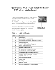
Check Battery Power and CMOS Initialize interrupt controlling hardware/vector table Initialize system timer Fixes CPU POST interface calling pointer Primary initialization of CPU Secondary initialization of CPU Set up boot strap processor information Set up boot strap processor for POST Enumerate and set up application processors Re-enable cache for the EVGA P55 Micro Motherboard during system boot up. The POST Codes are displayed on the Debug LED readout located directly onboard the motherboard. Code AMI POST Code Description 03 04 05 06...
Check Battery Power and CMOS Initialize interrupt controlling hardware/vector table Initialize system timer Fixes CPU POST interface calling pointer Primary initialization of CPU Secondary initialization of CPU Set up boot strap processor information Set up boot strap processor for POST Enumerate and set up application processors Re-enable cache for the EVGA P55 Micro Motherboard during system boot up. The POST Codes are displayed on the Debug LED readout located directly onboard the motherboard. Code AMI POST Code Description 03 04 05 06...


