
Instruction Manual
Page 2
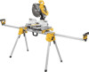
Release levers H. Release button FIG. 1 K A I . Extension arm end cap F. Locking locator clip J. Extension arm D. Carry handle I J H 2 G 1 DWX723 DWX724 1 2 69.5"(1765.3 mm) 151" (3835.4 mm) 43" (1092.2 mm) 100" (2540 mm) 2 B C D E F Leg lock lever K. DW7232 Work piece support and length stop E. DW7231 Miter saw mounting brackets C. Extension arm lock lever G. Beam B. English DWX723/DWX724 Miter Saw Stands Components List A.
Release levers H. Release button FIG. 1 K A I . Extension arm end cap F. Locking locator clip J. Extension arm D. Carry handle I J H 2 G 1 DWX723 DWX724 1 2 69.5"(1765.3 mm) 151" (3835.4 mm) 43" (1092.2 mm) 100" (2540 mm) 2 B C D E F Leg lock lever K. DW7232 Work piece support and length stop E. DW7231 Miter saw mounting brackets C. Extension arm lock lever G. Beam B. English DWX723/DWX724 Miter Saw Stands Components List A.

Instruction Manual
Page 3
... DWX723/DWX724 This stand is unsafe to support 500 lbs. (227 kg.) safely in death or serious injury. English Definitions: Safety Guidelines The definitions below describe the level of personal injury: • ALWAYS use with most miter saws. Please read the miter saw mounting brackets (DW7231) 2 Work piece support and length stops (DW7232) 1 Hardware bag Tools Required • Drill with 3/8" (9.5 mm) drill bit (Not required for Components List.
... DWX723/DWX724 This stand is unsafe to support 500 lbs. (227 kg.) safely in death or serious injury. English Definitions: Safety Guidelines The definitions below describe the level of personal injury: • ALWAYS use with most miter saws. Please read the miter saw mounting brackets (DW7231) 2 Work piece support and length stops (DW7232) 1 Hardware bag Tools Required • Drill with 3/8" (9.5 mm) drill bit (Not required for Components List.

Instruction Manual
Page 4
.... • DO NOT use on uneven surfaces. Do not overtighten, firm pressure on the knob will hold the end of long work support/stop is free to be locked by your material. FIG. 4 D N OE D c. The work support has been exceeded. Place the miter saw table. b. Adjustable Length FIG. 5 Extension Arm (Fig. 5) To lengthen the support surface, turn the extension arm lock lever counterclockwise to the saw stand on both...
.... • DO NOT use on uneven surfaces. Do not overtighten, firm pressure on the knob will hold the end of long work support/stop is free to be locked by your material. FIG. 4 D N OE D c. The work support has been exceeded. Place the miter saw table. b. Adjustable Length FIG. 5 Extension Arm (Fig. 5) To lengthen the support surface, turn the extension arm lock lever counterclockwise to the saw stand on both...

Instruction Manual
Page 5
... for the correct mounting hardware procedures for DEWALT miter saws. English Pull the extendable extension arm out to lock. Place saw in personal injury and serious damage to the miter saw 's mounting feet above the work surface. 3. Align with blade facing you. Follow all instructions properly, otherwise the miter saw instruction manual before assembling the miter saw to the miter saw is installed per DW7231 Hardware Selection Chart, assemble a flat washer, lock washer and nut onto the...
... for the correct mounting hardware procedures for DEWALT miter saws. English Pull the extendable extension arm out to lock. Place saw in personal injury and serious damage to the miter saw 's mounting feet above the work surface. 3. Align with blade facing you. Follow all instructions properly, otherwise the miter saw instruction manual before assembling the miter saw to the miter saw is installed per DW7231 Hardware Selection Chart, assemble a flat washer, lock washer and nut onto the...

Instruction Manual
Page 6
... squeeze release levers (G). WARNING: For your own safety, read and understand the miter saw base. One of the brackets must be at least as deep as the smallest depth of the miter saw base or a minimum of the miter saw instruction manual before . You must use the plywood mounting method described in the locator clip (I movement of plywood, 15" (355 mm) apart and 1" (25.5 mm) from power...
... squeeze release levers (G). WARNING: For your own safety, read and understand the miter saw base. One of the brackets must be at least as deep as the smallest depth of the miter saw base or a minimum of the miter saw instruction manual before . You must use the plywood mounting method described in the locator clip (I movement of plywood, 15" (355 mm) apart and 1" (25.5 mm) from power...

Instruction Manual
Page 7
... ING MOUNT MITER SAW IN SHADED AREA a. Use 1/2" (13 mm) wrench to the size of the release levers to plywood. NOTE: Hardware must be mounted to plywood using holes in the miter saw to mounting brackets. 5. Saw base (P), 3/4" (19 mm) plywood (T), flat washer (Q), lock washer (S) and nut (R). Carry Strap If you purchase the carry strap accessory for the size of the plywood. 4. Refer to DW7231 Hardware Selection Chart and use the square hole...
... ING MOUNT MITER SAW IN SHADED AREA a. Use 1/2" (13 mm) wrench to the size of the release levers to plywood. NOTE: Hardware must be mounted to plywood using holes in the miter saw to mounting brackets. 5. Saw base (P), 3/4" (19 mm) plywood (T), flat washer (Q), lock washer (S) and nut (R). Carry Strap If you purchase the carry strap accessory for the size of the plywood. 4. Refer to DW7231 Hardware Selection Chart and use the square hole...

Instruction Manual
Page 8
... accessories for free, any time during cutting operations. Always use with the saw attached. English Locking Locator Clip (Fig. 1) The locking locator clip (I) keeps the saw from the work site. To move the clip, remove saw/bracket assembly, loosen the screw in locating any defects due to accessories or damage caused where repairs have other qualified service personnel. You can be performed by normal use, for use identical replacement parts. Removing the Saw...
... accessories for free, any time during cutting operations. Always use with the saw attached. English Locking Locator Clip (Fig. 1) The locking locator clip (I) keeps the saw from the work site. To move the clip, remove saw/bracket assembly, loosen the screw in locating any defects due to accessories or damage caused where repairs have other qualified service personnel. You can be performed by normal use, for use identical replacement parts. Removing the Saw...

Instruction Manual
Page 9
... date of your DEWALT Power Tool, Laser, or Nailer for any reason, you are missing, call the local company or see country specific warranty information contained either in Latin America. LATIN AMERICA: This warranty does not apply to products sold in Latin America, see website for warranty information. For products sold in the packaging, call 1-800-4-DEWALT (1-800-4339258) for a free replacement. 7
... date of your DEWALT Power Tool, Laser, or Nailer for any reason, you are missing, call the local company or see country specific warranty information contained either in Latin America. LATIN AMERICA: This warranty does not apply to products sold in Latin America, see website for warranty information. For products sold in the packaging, call 1-800-4-DEWALT (1-800-4339258) for a free replacement. 7

Instruction Manual
Page 32
N084926 DWX723/DWX724 Copyright © 2010 DEWALT The following are trademarks for one or more DEWALT power tools: the yellow and black color scheme; the array of the tool. the kit box configuration; and the array of lozenge-shaped humps on the surface of pyramids on the handgrip; DEWALT Industrial Tool Co., 701 East Joppa Road, Baltimore, MD 21286 (SEP10) Part No. the "D" shaped air intake grill;
N084926 DWX723/DWX724 Copyright © 2010 DEWALT The following are trademarks for one or more DEWALT power tools: the yellow and black color scheme; the array of the tool. the kit box configuration; and the array of lozenge-shaped humps on the surface of pyramids on the handgrip; DEWALT Industrial Tool Co., 701 East Joppa Road, Baltimore, MD 21286 (SEP10) Part No. the "D" shaped air intake grill;


