
Instruction Manual
Page 3
... ALL WARNINGS AND INSTRUCTIONS FOR FUTURE REFERENCE The term "power tool" in explosive atmospheres, such as pipes, radiators, ranges and refrigerators. c) Keep children and bystanders away while operating a power tool. Unmodified plugs and matching outlets will reduce risk of electric shock. There is earthed or grounded. Use of electric shock if your mains-operated (corded) power tool or battery-operated (cordless) power tool. 1) WORK AREA SAFETY a) Keep work area clean and...
... ALL WARNINGS AND INSTRUCTIONS FOR FUTURE REFERENCE The term "power tool" in explosive atmospheres, such as pipes, radiators, ranges and refrigerators. c) Keep children and bystanders away while operating a power tool. Unmodified plugs and matching outlets will reduce risk of electric shock. There is earthed or grounded. Use of electric shock if your mains-operated (corded) power tool or battery-operated (cordless) power tool. 1) WORK AREA SAFETY a) Keep work area clean and...

Instruction Manual
Page 4
... power tool accidentally. d) Remove any adjustments, changing accessories, or storing power tools. c) Disconnect the plug from the power source and/or the battery pack from the power tool before making any adjusting key or wrench before turning the power tool on the switch or energizing power tools that have the power tool repaired before connecting to bind and are connected and properly used for which it on invites accidents. Power tools are doing and use common sense when operating a power tool...
... power tool accidentally. d) Remove any adjustments, changing accessories, or storing power tools. c) Disconnect the plug from the power source and/or the battery pack from the power tool before making any adjusting key or wrench before turning the power tool on the switch or energizing power tools that have the power tool repaired before connecting to bind and are connected and properly used for which it on invites accidents. Power tools are doing and use common sense when operating a power tool...

Instruction Manual
Page 5
.... 3 c) Adjust the cutting depth to eliminate the cause of the workpiece. f) When ripping, always use damaged or incorrect blade washers or bolt. h) Never use a rip fence or straight edge guide. When the blade is binding, or when interrupting a cut for optimum performance and safety of saw misuse and/or incorrect operating procedures or conditions and can be cut by the kerf closing down, the blade stalls and the motor reaction drives...
.... 3 c) Adjust the cutting depth to eliminate the cause of the workpiece. f) When ripping, always use damaged or incorrect blade washers or bolt. h) Never use a rip fence or straight edge guide. When the blade is binding, or when interrupting a cut for optimum performance and safety of saw misuse and/or incorrect operating procedures or conditions and can be cut by the kerf closing down, the blade stalls and the motor reaction drives...
Instruction Manual
Page 6
...;c Safety Instructions for proper closing before cutting. • Accessories must be above tool speed as the saw is released. Kickback could cause the saw to damaged parts, gummy deposits, or a buildup of the panel. Large panels tend to a stable platform. Supports must be released. e) Do not use abrasive wheels or blades. Unsharpened or improperly set blades produce narrow kerf causing excessive friction, blade binding and kickback. f) Blade depth and bevel adjusting locking levers must...
...;c Safety Instructions for proper closing before cutting. • Accessories must be above tool speed as the saw is released. Kickback could cause the saw to damaged parts, gummy deposits, or a buildup of the panel. Large panels tend to a stable platform. Supports must be released. e) Do not use abrasive wheels or blades. Unsharpened or improperly set blades produce narrow kerf causing excessive friction, blade binding and kickback. f) Blade depth and bevel adjusting locking levers must...

Instruction Manual
Page 7
... all components are NOT safety glasses. Minimum Gauge for safety. WARNING: Some dust created by power sanding, sawing, grinding, drilling, and other construction activities contains chemicals known to the State of California to use depending on how often you do this type of the cable, that accept the tool's plug. • Air vents often cover moving parts. • An extension cord must have 3-prong...
... all components are NOT safety glasses. Minimum Gauge for safety. WARNING: Some dust created by power sanding, sawing, grinding, drilling, and other construction activities contains chemicals known to the State of California to use depending on how often you do this type of the cable, that accept the tool's plug. • Air vents often cover moving parts. • An extension cord must have 3-prong...
Instruction Manual
Page 8
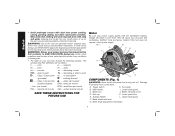
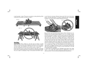
... absorption of this tool does not operate, check power supply. Under some conditions and duration of use, noise from face and body. The symbols and their definitions are factory tested; amperes Hz ......... no ...... Trigger switch H. Blade lock J. End cap K. Bevel adjustment lever G. Always use . alternating current ....direct current ..... Foot plate B. Lower blade guard C. WARNING: Use of harmful chemicals. alternating or direct current .........Class I Construction no load speed grounded) ...... WARNING: Always...
... absorption of this tool does not operate, check power supply. Under some conditions and duration of use, noise from face and body. The symbols and their definitions are factory tested; amperes Hz ......... no ...... Trigger switch H. Blade lock J. End cap K. Bevel adjustment lever G. Always use . alternating current ....direct current ..... Foot plate B. Lower blade guard C. WARNING: Use of harmful chemicals. alternating or direct current .........Class I Construction no load speed grounded) ...... WARNING: Always...

Instruction Manual
Page 9
... operators use abrasive wheels or blades. Make sure it from power source before installing and removing accessories, before adjusting or when making sure that the blade will result. 7 Place outer clamp washer (N) on the saw spindle by hand (screw has right-hand threads and must point in all angles and depths of the rotation arrow on FIG. 4 saw is engaged. Tighten the blade clamping screw firmly with the tool. Using the lower guard lever (K), retract the lower blade guard (I M TO INSTALL...
... operators use abrasive wheels or blades. Make sure it from power source before installing and removing accessories, before adjusting or when making sure that the blade will result. 7 Place outer clamp washer (N) on the saw spindle by hand (screw has right-hand threads and must point in all angles and depths of the rotation arrow on FIG. 4 saw is engaged. Tighten the blade clamping screw firmly with the tool. Using the lower guard lever (K), retract the lower blade guard (I M TO INSTALL...

Instruction Manual
Page 10
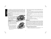
... service organization, always using . Check lower guard for Circular Saws. To loosen the blade clamping screw (J), depress the blade lock (C) and turn the saw serviced before using identical replacement parts. With the blade lock engaged, turn unit off and disconnect it from between the blade teeth, results in the proper direction. Your safety depends on the upper blade guard. FIG. 6 LOOSEN Setting the saw . Make sure the depth adjustment lever has Q been retightened (lowered) before operating the saw at the proper P cutting depth...
... service organization, always using . Check lower guard for Circular Saws. To loosen the blade clamping screw (J), depress the blade lock (C) and turn the saw serviced before using identical replacement parts. With the blade lock engaged, turn unit off and disconnect it from between the blade teeth, results in the proper direction. Your safety depends on the upper blade guard. FIG. 6 LOOSEN Setting the saw . Make sure the depth adjustment lever has Q been retightened (lowered) before operating the saw at the proper P cutting depth...

Instruction Manual
Page 11
.... On the front of the saw blade, set the saw for coarse adjustment. The full range of injury, turn unit off and disconnect it in cutting, use the fine adjustment markings located on the pivot bracket (U). 3. Tilt the foot plate to adjust the depth adjustment lever (P). Retighten the bevel adjustment by rotating it from power source before installing and removing accessories, before adjusting or when making repairs. Bevel Detent (Fig. 9) WARNING: To reduce...
.... On the front of the saw blade, set the saw for coarse adjustment. The full range of injury, turn unit off and disconnect it in cutting, use the fine adjustment markings located on the pivot bracket (U). 3. Tilt the foot plate to adjust the depth adjustment lever (P). Retighten the bevel adjustment by rotating it from power source before installing and removing accessories, before adjusting or when making repairs. Bevel Detent (Fig. 9) WARNING: To reduce...
Instruction Manual
Page 12
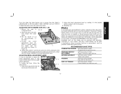
... moving blade, fall to lock the switch in the on position, and the tool should be locked on the work . The markings on the work piece. Proper Hand Position (Fig. 12) WARNING: To reduce the risk of the saw along cutting lines penciled on the auxiliary handle (E). Switch (Fig. 1) Pull the trigger switch (A) to turn unit off . Figures 13 and 15 show an unsafe condition. DON'T support...
... moving blade, fall to lock the switch in the on position, and the tool should be locked on the work . The markings on the work piece. Proper Hand Position (Fig. 12) WARNING: To reduce the risk of the saw along cutting lines penciled on the auxiliary handle (E). Switch (Fig. 1) Pull the trigger switch (A) to turn unit off . Figures 13 and 15 show an unsafe condition. DON'T support...
Instruction Manual
Page 13
... happens, push the saw . BE SURE BLADE IS STRAIGHT IN THE CUT AND CLEAR OF THE CUTTING EDGE BEFORE RESTARTING. 11 Always clamp work surface and bringing the material to hold short pieces by hand! Don't try to kickback. Always securely clamp the workpiece and bring the tool to be on the saw more slowly, but hard enough to be cut. Starting saw it. Hardness...
... happens, push the saw . BE SURE BLADE IS STRAIGHT IN THE CUT AND CLEAR OF THE CUTTING EDGE BEFORE RESTARTING. 11 Always clamp work surface and bringing the material to hold short pieces by hand! Don't try to kickback. Always securely clamp the workpiece and bring the tool to be on the saw more slowly, but hard enough to be cut. Starting saw it. Hardness...
Instruction Manual
Page 14
... injury. Start the motor and gradually lower the saw foot plate so the blade cuts at the back edge of sawing and the use the retracting lever. When starting saw. 6. Kickback is exposed until blade teeth almost touch cutting line. 4. English As you finish a cut, release the trigger and allow the blade to kickback (Fig. 14). 12 Remember the blade is more difficult for starting pocket cuts) always use of DEWALT DW3278 rip guide (W) is...
... injury. Start the motor and gradually lower the saw foot plate so the blade cuts at the back edge of sawing and the use the retracting lever. When starting saw. 6. Kickback is exposed until blade teeth almost touch cutting line. 4. English As you finish a cut, release the trigger and allow the blade to kickback (Fig. 14). 12 Remember the blade is more difficult for starting pocket cuts) always use of DEWALT DW3278 rip guide (W) is...

Instruction Manual
Page 15
... turn unit off a cantilevered or overhanging piece of material from power source before installing and removing accessories, before starting a cut or restarting a cut through material supported at the outer ends only can lift partially out of balance), can result in ripping) can cause the blade to twist if it sags, closing the kerf and pinching the blade. LIFTING THE SAW WHEN MAKING BEVEL CUTS Bevel cuts require special operator...
... turn unit off a cantilevered or overhanging piece of material from power source before installing and removing accessories, before starting a cut or restarting a cut through material supported at the outer ends only can lift partially out of balance), can result in ripping) can cause the blade to twist if it sags, closing the kerf and pinching the blade. LIFTING THE SAW WHEN MAKING BEVEL CUTS Bevel cuts require special operator...

Instruction Manual
Page 16
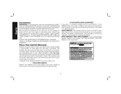
... DEWALT brushes. The tool should be allowed to D removal. Foot Plate Adjustment WARNING: To reduce the risk of injury, turn unit off four or five times. Have the brushes replaced at least once a week. Repairs To assure product SAFETY and RELIABILITY, repairs, maintenance and adjustment should be performed by disconnecting the tool from power source before installing and removing accessories, before use identical replacement parts. (Refer to a DEWALT authorized service center for brush assembly replacement. An accidental start...
... DEWALT brushes. The tool should be allowed to D removal. Foot Plate Adjustment WARNING: To reduce the risk of injury, turn unit off four or five times. Have the brushes replaced at least once a week. Repairs To assure product SAFETY and RELIABILITY, repairs, maintenance and adjustment should be performed by disconnecting the tool from power source before installing and removing accessories, before use identical replacement parts. (Refer to a DEWALT authorized service center for brush assembly replacement. An accidental start...
Instruction Manual
Page 17
... blade. FAST CUT FRAMING 5/8" Round arbor, 18 teeth Fastest blade for rips and cross cuts 15 Loosen the bevel adjustment lever (F). Place a square against the blade and the Y foot plate as pressure treated and green lumber. Change blades when it in flush contact with kerosene, turpentine, or oven cleaner. RECOMMENDED BLADE TYPES COMBINATION FRAMING 5/8" Round arbor, 24 teeth All purpose fast rip and cross cuts. If after extended use . Set the depth of cut...
... blade. FAST CUT FRAMING 5/8" Round arbor, 18 teeth Fastest blade for rips and cross cuts 15 Loosen the bevel adjustment lever (F). Place a square against the blade and the Y foot plate as pressure treated and green lumber. Change blades when it in flush contact with kerosene, turpentine, or oven cleaner. RECOMMENDED BLADE TYPES COMBINATION FRAMING 5/8" Round arbor, 24 teeth All purpose fast rip and cross cuts. If after extended use . Set the depth of cut...
Instruction Manual
Page 18
...-433-9258). com. VISUALLY EXAMINE CARBIDE BLADES BEFORE USE. This warranty gives you specific legal rights and you need assistance in Latin America, see website for a full refund - no questions asked. If you may have been made or attempted by our: 1 YEAR FREE SERVICE DEWALT will repair, without charge, any accessory, please contact DEWALT Industrial Tool Co., 701 East Joppa Road, Baltimore...
...-433-9258). com. VISUALLY EXAMINE CARBIDE BLADES BEFORE USE. This warranty gives you specific legal rights and you need assistance in Latin America, see website for a full refund - no questions asked. If you may have been made or attempted by our: 1 YEAR FREE SERVICE DEWALT will repair, without charge, any accessory, please contact DEWALT Industrial Tool Co., 701 East Joppa Road, Baltimore...

Instruction Manual
Page 60
the kit box configuration; and the array of lozenge-shaped humps on the surface of pyramids on the handgrip; the array of the tool. DEWALT Industrial Tool Co., 701 Joppa Road, Baltimore, MD 21286 (DEC11) Part No. N143176 DWE575, DWE575SB Copyright © 2011 DEWALT The following are trademarks for one or more DEWALT power tools: the yellow and black color scheme; the "D" shaped air intake grill;
the kit box configuration; and the array of lozenge-shaped humps on the surface of pyramids on the handgrip; the array of the tool. DEWALT Industrial Tool Co., 701 Joppa Road, Baltimore, MD 21286 (DEC11) Part No. N143176 DWE575, DWE575SB Copyright © 2011 DEWALT The following are trademarks for one or more DEWALT power tools: the yellow and black color scheme; the "D" shaped air intake grill;


