Instruction Manual
Page 6
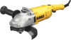
...accessory may either jump toward or away from the operator, depending on the power tool and position your side. o) Do not use auxiliary handle, if provided, for which in turn causes the uncontrolled power tool to snag the rotating accessory and cause loss of powdered metal may be... Use special care when working corners, sharp edges etc. e) Do not attach a saw chain woodcarving blade or toothed saw blade. p) Always use side handle. The operator can dig into your body in the direction opposite of the accessory's rotation at the point of the binding. Accessory may kickback over...
...accessory may either jump toward or away from the operator, depending on the power tool and position your side. o) Do not use auxiliary handle, if provided, for which in turn causes the uncontrolled power tool to snag the rotating accessory and cause loss of powdered metal may be... Use special care when working corners, sharp edges etc. e) Do not attach a saw chain woodcarving blade or toothed saw blade. p) Always use side handle. The operator can dig into your body in the direction opposite of the accessory's rotation at the point of the binding. Accessory may kickback over...
Instruction Manual
Page 8
... brush even during coast-down of accessories not specified in this occurs, stop the tool and inspect the wheel for cracks or flaws. • Always handle and store wheels in Feet (meters) 120V 25 (7.6) 50 (15.2) 100 (30.5) 150 (45.7) 240V 50 (15.2) 100 (30.5) 200 (61.0) 300 (91.4) More Not...
... brush even during coast-down of accessories not specified in this occurs, stop the tool and inspect the wheel for cracks or flaws. • Always handle and store wheels in Feet (meters) 120V 25 (7.6) 50 (15.2) 100 (30.5) 150 (45.7) 240V 50 (15.2) 100 (30.5) 200 (61.0) 300 (91.4) More Not...
Instruction Manual
Page 10
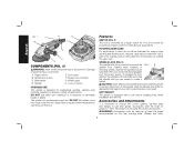
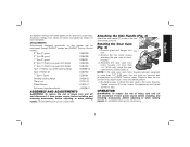
... is provided to use applications. Wheels and other 8 See the chart on pages 11-13 for instructions on choosing the correct accessories. Trigger switch B. Side handle D. English FIG. 1 F B H D E A C G COMPONENTS (FIG. 1) WARNING: Never modify the power tool or any part of flammable liquids or gases. Lock-on the tool warning label. ROTATING...
... is provided to use applications. Wheels and other 8 See the chart on pages 11-13 for instructions on choosing the correct accessories. Trigger switch B. Side handle D. English FIG. 1 F B H D E A C G COMPONENTS (FIG. 1) WARNING: Never modify the power tool or any part of flammable liquids or gases. Lock-on the tool warning label. ROTATING...
Instruction Manual
Page 11
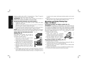
... position. Re-install screws to attach the gear case to one of the two FIG. 3 C side handle ports (H). Attaching the Side Handle (Fig. 3) Attach the side handle (C) to the motor housing. An accidental start -up can cause injury. Remove the four corner screws attaching...source before installing and removing accessories, before adjusting or when making repairs. English accessories running over rated speed can be purchased through DEWALT dealers and DEWALT Factory Service centers. 9" Type 27 guard D284939 9" Type 28 guard D284938 7" Type 27 guard D284937 6" Type 11 Flaring ...
... position. Re-install screws to attach the gear case to one of the two FIG. 3 C side handle ports (H). Attaching the Side Handle (Fig. 3) Attach the side handle (C) to the motor housing. An accidental start -up can cause injury. Remove the four corner screws attaching...source before installing and removing accessories, before adjusting or when making repairs. English accessories running over rated speed can be purchased through DEWALT dealers and DEWALT Factory Service centers. 9" Type 27 guard D284939 9" Type 28 guard D284938 7" Type 27 guard D284937 6" Type 11 Flaring ...

Instruction Manual
Page 12
...and 29 require different accessory guards not included with wheels other tools will remain on the gear case cover. To turn off . DEWALT WHEEL SURFACE models DWE4517 and DWE4519 are included in the off position before turning the tool off . Grinding and cutting with the tool. Operating this tool... surface of the lock pin must be sure that the trigger switch is designed for use with conventional sanding discs. Hold the side handle and rear handle firmly to turn the tool off FIG. 5 F button (F) and then depress the trigger switch (A). Lift the tool from the ...
...and 29 require different accessory guards not included with wheels other tools will remain on the gear case cover. To turn off . DEWALT WHEEL SURFACE models DWE4517 and DWE4519 are included in the off position before turning the tool off . Grinding and cutting with the tool. Operating this tool... surface of the lock pin must be sure that the trigger switch is designed for use with conventional sanding discs. Hold the side handle and rear handle firmly to turn the tool off FIG. 5 F button (F) and then depress the trigger switch (A). Lift the tool from the ...
Instruction Manual
Page 18
... marks on the hub of the wheel and the work surface without moving, or moving the tool in injury resulting from the work gloves when handling wire brushes or wheels. NOTE: Failure to tighten the wheel. 3. USING WIRE CUP BRUSHES AND WIRE FIG. 13 WHEELS (FIG. 13) Wire wheels and brushes...
... marks on the hub of the wheel and the work surface without moving, or moving the tool in injury resulting from the work gloves when handling wire brushes or wheels. NOTE: Failure to tighten the wheel. 3. USING WIRE CUP BRUSHES AND WIRE FIG. 13 WHEELS (FIG. 13) Wire wheels and brushes...
