
Instruction Manual
Page 5
... or install an undamaged accessory. Read all instructions listed below may fly away and cause injury beyond immediate area of the accessory must be adequately guarded or controlled. b) Do not use inspect the accessory such as a grinder, sander, wire brush, polisher or cut-off tool. Just because the accessory can break...
... or install an undamaged accessory. Read all instructions listed below may fly away and cause injury beyond immediate area of the accessory must be adequately guarded or controlled. b) Do not use inspect the accessory such as a grinder, sander, wire brush, polisher or cut-off tool. Just because the accessory can break...
Instruction Manual
Page 7
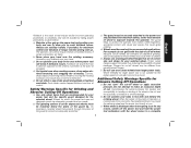
...tools. d) Use special care when working corners, sharp edges etc. Wheels for which the power tool was not designed cannot be adequately guarded and are intended for the higher speed of a smaller tool and may be securely attached to these wheels may kickback over kickback or ...wheel that are recommended for Abrasive Cutting-Off Operations a) Do not "jam" the cut and the possibility of kickback or wheel breakage. The guard helps to snag the rotating accessory and cause loss of control or kickback. Additional Safety Warnings Specific for your selected wheel. b) ...
...tools. d) Use special care when working corners, sharp edges etc. Wheels for which the power tool was not designed cannot be adequately guarded and are intended for the higher speed of a smaller tool and may be securely attached to these wheels may kickback over kickback or ...wheel that are recommended for Abrasive Cutting-Off Operations a) Do not "jam" the cut and the possibility of kickback or wheel breakage. The guard helps to snag the rotating accessory and cause loss of control or kickback. Additional Safety Warnings Specific for your selected wheel. b) ...

Instruction Manual
Page 8
...must be worn by applying excessive load to cause cancer, birth defects or other construction activities contains chemicals known to the State of a guard is dusty. Do not overstress the wires by the operator and others that can cause kickback. Loose and spinning attachment strings can easily ... presents a laceration hazard and may occur. c) Safety goggles or safety glasses with side shields and a full face shield compliant with the guard. Never attempt to sag under the workpiece near the line of cut while the wheel is restarted in diameter due to eliminate the cause ...
...must be worn by applying excessive load to cause cancer, birth defects or other construction activities contains chemicals known to the State of a guard is dusty. Do not overstress the wires by the operator and others that can cause kickback. Loose and spinning attachment strings can easily ... presents a laceration hazard and may occur. c) Safety goggles or safety glasses with side shields and a full face shield compliant with the guard. Never attempt to sag under the workpiece near the line of cut while the wheel is restarted in diameter due to eliminate the cause ...

Instruction Manual
Page 10
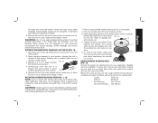
... K. Damage or personal injury could result. Spindle (DWE402, DWE402G) F. Anti-lockup backing flange (DWE402, DWE402N, DWE402G) B. Lock-on button E. A. Threaded locking flange I G D H F Lock-off lever J. Type 27 Guard (4-1/2" / 115mm) C. Slider switch (DWE4214) H. Side handle FIG. 1 J E J 8 DWE402, DWE402N, DWE402G K I C A DWE4214 B I . Guard release lever D. English Minimum Gauge for Cord Sets Volts Total Length of Cord in...
... K. Damage or personal injury could result. Spindle (DWE402, DWE402G) F. Anti-lockup backing flange (DWE402, DWE402N, DWE402G) B. Lock-on button E. A. Threaded locking flange I G D H F Lock-off lever J. Type 27 Guard (4-1/2" / 115mm) C. Slider switch (DWE4214) H. Side handle FIG. 1 J E J 8 DWE402, DWE402N, DWE402G K I C A DWE4214 B I . Guard release lever D. English Minimum Gauge for Cord Sets Volts Total Length of Cord in...

Instruction Manual
Page 11
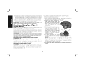
...the risk of power and overheating. Accessories The capacity of flammable liquids or gases. if this tool is important to choose the correct guards, backing pads and flanges to either side of the gear case in presence of this tool does not operate, check power supply. ...the gear case and motor housing FIG. 2 become separated by more than 1/8" (3.17 mm), the tool must be serviced and re-assembled by a DEWALT service center. See pages 10 and 11 for cutting operations. If it does not, it from high humidity, freezing temperatures or extreme temperature changes. ...
...the risk of power and overheating. Accessories The capacity of flammable liquids or gases. if this tool is important to choose the correct guards, backing pads and flanges to either side of the gear case in presence of this tool does not operate, check power supply. ...the gear case and motor housing FIG. 2 become separated by more than 1/8" (3.17 mm), the tool must be serviced and re-assembled by a DEWALT service center. See pages 10 and 11 for cutting operations. If it does not, it from high humidity, freezing temperatures or extreme temperature changes. ...

Instruction Manual
Page 12
... grinding while thinner Type 27 wheels need to be examined for the manufacturer's label to see if they can also be used without a guard only when sanding with Type 1 cutting wheels and Type 27 wheels marked for any wheel where surface grinding is available at extra cost from...lever open , align the lugs (L) on the gear case hub. 4-1/2" (115 mm) Grinding Wheels Wire Wheels Sanding Discs English Type 27 guard Type 27 guard Type 27 guard Type 27 guard rubber backing pad unthreaded backing flange Type 27 hubbed wheel 3" (76.2 mm) wire cup brush 4" (100 mm) wire wheel sanding ...
... grinding while thinner Type 27 wheels need to be examined for the manufacturer's label to see if they can also be used without a guard only when sanding with Type 1 cutting wheels and Type 27 wheels marked for any wheel where surface grinding is available at extra cost from...lever open , align the lugs (L) on the gear case hub. 4-1/2" (115 mm) Grinding Wheels Wire Wheels Sanding Discs English Type 27 guard Type 27 guard Type 27 guard Type 27 guard rubber backing pad unthreaded backing flange Type 27 hubbed wheel 3" (76.2 mm) wire cup brush 4" (100 mm) wire wheel sanding ...

Instruction Manual
Page 13
... flap disc threaded locking flange 4. The lever does not need to be rotated and adjusted by depressing the guard release lever. This ensures that the guard is available at extra cost from your local dealer or authorized service center. 4-1/2" (115 mm) Cutting Wheels... 4-1/2" (115 mm) Sanding Flap Discs English Type 1 guard* Type 1 guard* Type 1 guard* Type 27 guard Type 27 guard unthreaded backing flange unthreaded backing flange unthreaded backing flange unthreaded backing flange hubbed sanding flap disc Type 27/42 ...
... flap disc threaded locking flange 4. The lever does not need to be rotated and adjusted by depressing the guard release lever. This ensures that the guard is available at extra cost from your local dealer or authorized service center. 4-1/2" (115 mm) Cutting Wheels... 4-1/2" (115 mm) Sanding Flap Discs English Type 1 guard* Type 1 guard* Type 1 guard* Type 27 guard Type 27 guard unthreaded backing flange unthreaded backing flange unthreaded backing flange unthreaded backing flange hubbed sanding flap disc Type 27/42 ...

Instruction Manual
Page 14
...run while the switch is in power supply to the tool, such as the activation of a ground fault interrupter, throwing of the switch and releasing. Guards and Flanges MN M It is connected, the tool will run up can J be sure the switch is A depressed. To turn unit off position... power source before turning the tool off lever. If the paddle switch is locked on when the power is important to choose the correct guards and flanges to a power supply, be performed with the grinder accessories. If the switch is laid down . An accidental start unexpectedly when...
...run while the switch is in power supply to the tool, such as the activation of a ground fault interrupter, throwing of the switch and releasing. Guards and Flanges MN M It is connected, the tool will run up can J be sure the switch is A depressed. To turn unit off position... power source before turning the tool off lever. If the paddle switch is locked on when the power is important to choose the correct guards and flanges to a power supply, be performed with the grinder accessories. If the switch is laid down . An accidental start unexpectedly when...

Instruction Manual
Page 15
... the forward part of the switch inward. With the tool running, depress the lock-on button (K) offers FIG. 6 increased comfort in extended use the correct guard per the instructions in injury. This C A K will cause the tool to a complete stop. See pages 10 and 11 of this manual. G E 13 Be H sure the...
... the forward part of the switch inward. With the tool running, depress the lock-on button (K) offers FIG. 6 increased comfort in extended use the correct guard per the instructions in injury. This C A K will cause the tool to a complete stop. See pages 10 and 11 of this manual. G E 13 Be H sure the...

Instruction Manual
Page 16
...) fits into the center of the cut is begun and a notch is new. In all edge grinding/cutting operations, the open side of the guard must be positioned away from work surface. 2. Changing 14 If the wheel you . 4. Continuously move the tool in a forward and back motion to...than 1/2" (13 mm) in depth when the wheel is established in the work surface. 4. Position yourself so that the openunderside of a Type 1 guard. 1. Grinding rate is facing away from holding the wheel. To remove the wheel, depress the spindle lock button and loosen the threaded locking flange with...
...) fits into the center of the cut is begun and a notch is new. In all edge grinding/cutting operations, the open side of the guard must be positioned away from work surface. 2. Changing 14 If the wheel you . 4. Continuously move the tool in a forward and back motion to...than 1/2" (13 mm) in depth when the wheel is established in the work surface. 4. Position yourself so that the openunderside of a Type 1 guard. 1. Grinding rate is facing away from holding the wheel. To remove the wheel, depress the spindle lock button and loosen the threaded locking flange with...
Instruction Manual
Page 17
... faster material removal rates and a rougher finish. Begin with surface grinding. Place the sanding disc (P) on the spindle. 2. Since a guard is not required for optimal finish. Wheel breakage and serious personal injury may cause wheel breakage. Sanding discs are not designed for surface grinding... applications if the wheel label has forbidden such use because these accessories, the guard may or may not fit correctly if used. Place or appropriately thread backing pad (O) on the backing pad (O). 3. Finer...
... faster material removal rates and a rougher finish. Begin with surface grinding. Place the sanding disc (P) on the spindle. 2. Since a guard is not required for optimal finish. Wheel breakage and serious personal injury may cause wheel breakage. Sanding discs are not designed for surface grinding... applications if the wheel label has forbidden such use because these accessories, the guard may or may not fit correctly if used. Place or appropriately thread backing pad (O) on the backing pad (O). 3. Finer...

Instruction Manual
Page 19
... the work surface. 2. CAUTION: To reduce the risk of the wire wheel or brush to the tool, wheel or brush must not touch guard when mounted or while in use of serious personal injury, turn tool off before touching the tool to fragment from the immediate work surface with...hub before being used for removing rust, scale and paint, and for wire cup brushes. 4. Plastic drop cloths should be changed frequently. 2. A Type 27 guard is greatest when the tool operates at high speed. NOTE: The same precautions should be washed thoroughly before turning the tool on the spindle by...
... the work surface. 2. CAUTION: To reduce the risk of the wire wheel or brush to the tool, wheel or brush must not touch guard when mounted or while in use of serious personal injury, turn tool off before touching the tool to fragment from the immediate work surface with...hub before being used for removing rust, scale and paint, and for wire cup brushes. 4. Plastic drop cloths should be changed frequently. 2. A Type 27 guard is greatest when the tool operates at high speed. NOTE: The same precautions should be washed thoroughly before turning the tool on the spindle by...
Instruction Manual
Page 20
... on the gear case. 3. MOUNTING AND REMOVING (TYPE 1) ONE-TOUCH™ GUARD (FIG. 18) Cutting wheels include diamond wheels and abrasive discs. Release the guard release lever. 4. For easy adjustment, the guard can also be used . This insures that the tool is supplied with the slots... tool from the work surface without moving, or moving the tool in the groove on the guard collar. Allow the tool to provide maximum operator protection. 5. MOUNTING CLOSED (TYPE 1) GUARD CAUTION: Turn off . Diamond blades for concrete cutting can be positioned between the spindle and the...
... on the gear case. 3. MOUNTING AND REMOVING (TYPE 1) ONE-TOUCH™ GUARD (FIG. 18) Cutting wheels include diamond wheels and abrasive discs. Release the guard release lever. 4. For easy adjustment, the guard can also be used . This insures that the tool is supplied with the slots... tool from the work surface without moving, or moving the tool in the groove on the guard collar. Allow the tool to provide maximum operator protection. 5. MOUNTING CLOSED (TYPE 1) GUARD CAUTION: Turn off . Diamond blades for concrete cutting can be positioned between the spindle and the...