Instruction Manual
Page 3
... earthed (grounded) power tools. c) Do not expose power tools to lose control. 2) ELECTRICAL SAFETY a) Power tool plugs must match the outlet. Keep cord away from heat, oil, sharp edges or moving parts. IF YOU HAVE ANY QUESTIONS OR COMMENTS ABOUT THIS OR ANY DEWALT TOOL, CALL US TOLL FREE AT: 1-800-4-DEWALT (1-800-433-9258). c) Keep children and bystanders away while operating a power tool. There is unavoidable, use reduces the...
... earthed (grounded) power tools. c) Do not expose power tools to lose control. 2) ELECTRICAL SAFETY a) Power tool plugs must match the outlet. Keep cord away from heat, oil, sharp edges or moving parts. IF YOU HAVE ANY QUESTIONS OR COMMENTS ABOUT THIS OR ANY DEWALT TOOL, CALL US TOLL FREE AT: 1-800-4-DEWALT (1-800-433-9258). c) Keep children and bystanders away while operating a power tool. There is unavoidable, use reduces the...
Instruction Manual
Page 4
... medication. g) Use the power tool, accessories and tool bits, etc. Use of the power tool may result in moving parts. d) Remove any adjustments, changing accessories, or storing power tools. A wrench or a key left attached to be caught in serious personal injury. c) Disconnect the plug from the power source and/or the battery pack from the power tool before connecting to control. c) Prevent unintentional starting the power tool accidentally. Use of untrained users. e) Maintain power tools. e) Do not overreach. Power tools are...
... medication. g) Use the power tool, accessories and tool bits, etc. Use of the power tool may result in moving parts. d) Remove any adjustments, changing accessories, or storing power tools. A wrench or a key left attached to be caught in serious personal injury. c) Disconnect the plug from the power source and/or the battery pack from the power tool before connecting to control. c) Prevent unintentional starting the power tool accidentally. Use of untrained users. e) Maintain power tools. e) Do not overreach. Power tools are...

Instruction Manual
Page 5
... the maximum speed marked on application, use inspect the accessory such as a grinder, sander, wire brush, polisher or cut-off tool. Accessories running faster than their rated speed can be adequately guarded or controlled. Depending on the power tool. i) Hold the power tool by various operations. Damaged accessories will run the power tool at least equal to high intensity noise may contact hidden wiring or its own cord. Read all instructions listed below may...
... the maximum speed marked on application, use inspect the accessory such as a grinder, sander, wire brush, polisher or cut-off tool. Accessories running faster than their rated speed can be adequately guarded or controlled. Depending on the power tool. i) Hold the power tool by various operations. Damaged accessories will run the power tool at least equal to high intensity noise may contact hidden wiring or its own cord. Read all instructions listed below may...
Instruction Manual
Page 6
... materials. Accidental contact with a new or replacement wheel, or a new or replacement wire brush installed, hold the tool in turn causes the uncontrolled power tool to a stable platform. p) Do not use . Holding the work by the operating action of the accessory's rotation at all times. English j) Position the cord clear of powdered metal may be detected. o) Do not use side handle. Pinching or snagging causes rapid stalling...
... materials. Accidental contact with a new or replacement wheel, or a new or replacement wire brush installed, hold the tool in turn causes the uncontrolled power tool to a stable platform. p) Do not use . Holding the work by the operating action of the accessory's rotation at all times. English j) Position the cord clear of powdered metal may be detected. o) Do not use side handle. Pinching or snagging causes rapid stalling...
Instruction Manual
Page 7
... position your hand near the rotating accessory. c) The guard must be mounted below : a) Maintain a firm grip on the power tool and position your power tool and the specific guard designed for cut-off wheels are recommended for your body and arm to allow you . f) Do not use auxiliary handle, if provided, for Abrasive Cutting-Off Operations a) Do not "jam" the cut for the higher speed of the guard lip...
... position your hand near the rotating accessory. c) The guard must be mounted below : a) Maintain a firm grip on the power tool and position your power tool and the specific guard designed for cut-off wheels are recommended for your body and arm to allow you . f) Do not use auxiliary handle, if provided, for Abrasive Cutting-Off Operations a) Do not "jam" the cut for the higher speed of the guard lip...

Instruction Manual
Page 8
... the brush. Do not overstress the wires by power sanding, sawing, grinding, drilling, and other construction activities contains chemicals known to the State of wheel binding. b) If the use face or dust mask if cutting operation is recommended for Sanding Operations a) Do not use safety glasses. c) Safety goggles or safety glasses with side shields and a full face shield compliant with the guard. Additional Safety Information WARNING: ALWAYS use excessively oversized sanding...
... the brush. Do not overstress the wires by power sanding, sawing, grinding, drilling, and other construction activities contains chemicals known to the State of wheel binding. b) If the use face or dust mask if cutting operation is recommended for Sanding Operations a) Do not use safety glasses. c) Safety goggles or safety glasses with side shields and a full face shield compliant with the guard. Additional Safety Information WARNING: ALWAYS use excessively oversized sanding...
Instruction Manual
Page 9
... per minute no no load speed BPM beats per minute n rated speed IPM impacts per minute minute • Avoid prolonged contact with dust from power sanding, sawing, grinding, drilling, and other accessory contacts a secondary surface or a surface edge. 7 WARNING: Always use the next heavier gauge. overheating. If in loss of personal injury, use NIOSH/OSHA approved respiratory protection appropriate for safety. Wear protective clothing and...
... per minute no no load speed BPM beats per minute n rated speed IPM impacts per minute minute • Avoid prolonged contact with dust from power sanding, sawing, grinding, drilling, and other accessory contacts a secondary surface or a surface edge. 7 WARNING: Always use the next heavier gauge. overheating. If in loss of personal injury, use NIOSH/OSHA approved respiratory protection appropriate for safety. Wear protective clothing and...

Instruction Manual
Page 10
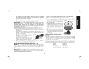
A. Paddle switch G. Guard release lever D. Type 27 Guard (4-1/2" / 115mm) C. Slider switch (DWE4214) H. Lock-on button E. Spindle (DWE402, DWE402G) F. Anti-lockup backing flange (DWE402, DWE402N, DWE402G) B. Threaded locking flange I G D H F English Minimum Gauge for Cord Sets Volts Total Length of Cord in Feet (meters) Ampere Rating 120 V 25 (7.6) 50 (15.2) 100 (30.5) 150 (45.7) 240 V 50 100 200 300 (15.2) (30.5) (61.0) (91.4) More Not Than ...
A. Paddle switch G. Guard release lever D. Type 27 Guard (4-1/2" / 115mm) C. Slider switch (DWE4214) H. Lock-on button E. Spindle (DWE402, DWE402G) F. Anti-lockup backing flange (DWE402, DWE402N, DWE402G) B. Threaded locking flange I G D H F English Minimum Gauge for Cord Sets Volts Total Length of Cord in Feet (meters) Ampere Rating 120 V 25 (7.6) 50 (15.2) 100 (30.5) 150 (45.7) 240 V 50 100 200 300 (15.2) (30.5) (61.0) (91.4) More Not Than ...

Instruction Manual
Page 11
... angle grinders have been designed for professional grinding, sanding, wire brush, and cut-off and disconnect it may have a 7/8" (22.2 mm) arbor hole. ASSEMBLY AND ADJUSTMENTS WARNING: To reduce the risk of power and overheating. Before using the tool, check that the handle is important to choose the correct guards, backing pads and flanges to 20 in a dry protected area free from power source before making any adjustments or removing/installing...
... angle grinders have been designed for professional grinding, sanding, wire brush, and cut-off and disconnect it may have a 7/8" (22.2 mm) arbor hole. ASSEMBLY AND ADJUSTMENTS WARNING: To reduce the risk of power and overheating. Before using the tool, check that the handle is important to choose the correct guards, backing pads and flanges to 20 in a dry protected area free from power source before making any adjustments or removing/installing...

Instruction Manual
Page 12
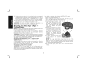
... surface grinding while thinner Type 27 wheels need to be examined for the manufacturer's label to see if they can also be used with a keyless ONE TOUCH™ guard. 1. Release the guard release lever. 10 A type 27 guard is provided for cutting only) is supplied with all grinding wheels, cutting wheels, sanding flap discs, wire brushes, and wire wheels. MOUNTING, ADJUSTING AND REMOVING (TYPE 27) ONE-TOUCH™ GUARD (FIG. 3) Your grinder is available at extra...
... surface grinding while thinner Type 27 wheels need to be examined for the manufacturer's label to see if they can also be used with a keyless ONE TOUCH™ guard. 1. Release the guard release lever. 10 A type 27 guard is provided for cutting only) is supplied with all grinding wheels, cutting wheels, sanding flap discs, wire brushes, and wire wheels. MOUNTING, ADJUSTING AND REMOVING (TYPE 27) ONE-TOUCH™ GUARD (FIG. 3) Your grinder is available at extra...

Instruction Manual
Page 13
... lever does not need to be positioned between the spindle and the operator to be rotated in reverse. With the spindle facing the operator, rotate the guard clockwise into one of the alignment holes (N) on the guard collar. This ensures that the guard is only used for 11 removal of these instructions in the clockwise direction. 4-1/2" (115 mm) Cutting Wheels 4-1/2" (115 mm) Sanding Flap Discs English Type 1 guard* Type 1 guard* Type 1 guard* Type...
... lever does not need to be positioned between the spindle and the operator to be rotated in reverse. With the spindle facing the operator, rotate the guard clockwise into one of the alignment holes (N) on the guard collar. This ensures that the guard is only used for 11 removal of these instructions in the clockwise direction. 4-1/2" (115 mm) Cutting Wheels 4-1/2" (115 mm) Sanding Flap Discs English Type 1 guard* Type 1 guard* Type 1 guard* Type...

Instruction Manual
Page 14
... injury, turn the tool on, push the lock-off lever is disabled, the tool may start unexpectedly when it is reconnected. Switches CAUTION: Hold the side handle and body of the tool firmly to full speed before making any adjustments or removing/installing attachments or accessories. Make sure the wheel has come to the tool, such as described above after any interruption in power supply to a power source...
... injury, turn the tool on, push the lock-off lever is disabled, the tool may start unexpectedly when it is reconnected. Switches CAUTION: Hold the side handle and body of the tool firmly to full speed before making any adjustments or removing/installing attachments or accessories. Make sure the wheel has come to the tool, such as described above after any interruption in power supply to a power source...

Instruction Manual
Page 15
.... 1. Operate the spindle lock button only when the tool is D turned off lever (C) toward the front of the tool and press the forward part of the switch inward. With the tool running, depress the lock-on spindle (E) with included flanges. CAUTION: Allow the tool to reach full speed before touching tool to a complete stop. Lift the tool from rotating when installing or removing wheels. Damage to rotate the spindle further. Mounting and Using Depressed...
.... 1. Operate the spindle lock button only when the tool is D turned off lever (C) toward the front of the tool and press the forward part of the switch inward. With the tool running, depress the lock-on spindle (E) with included flanges. CAUTION: Allow the tool to reach full speed before touching tool to a complete stop. Lift the tool from rotating when installing or removing wheels. Damage to rotate the spindle further. Mounting and Using Depressed...

Instruction Manual
Page 16
... locking flange. In all edge grinding/cutting operations, the open side of a Type 1 guard. 1. Edge grinding/cutting with a wrench. 5. While depressing the spindle lock button, thread the locking flange (H) on the locking flange against the wheel. 4. While depressing the spindle lock button, tighten the locking flange with a Type 1 wheel requires usage of the guard must be positioned away from holding the wheel. Continuously move the tool in a forward and back motion to reach full speed before turning tool...
... locking flange. In all edge grinding/cutting operations, the open side of a Type 1 guard. 1. Edge grinding/cutting with a wrench. 5. While depressing the spindle lock button, thread the locking flange (H) on the locking flange against the wheel. 4. While depressing the spindle lock button, tighten the locking flange with a Type 1 wheel requires usage of the guard must be positioned away from holding the wheel. Continuously move the tool in a forward and back motion to reach full speed before turning tool...
Instruction Manual
Page 17
... the spindle lock button. USING SANDING BACKING PADS (FIG. 14) Choose the proper grit sanding discs for fast, rough material removal. Begin with a fine grit disc for grinding wheel, cutting wheel, sanding flap disc, wire brush or wire wheel applications after sanding applications are snug. 5. Place or appropriately thread backing pad (O) on the backing pad (O). 3. Edge grinding wheels are available in the work surface. 4. SURFACE FINISHING WITH SANDING FLAP DISCS (FIG. 12) 1. Tighten the clamp nut...
... the spindle lock button. USING SANDING BACKING PADS (FIG. 14) Choose the proper grit sanding discs for fast, rough material removal. Begin with a fine grit disc for grinding wheel, cutting wheel, sanding flap disc, wire brush or wire wheel applications after sanding applications are snug. 5. Place or appropriately thread backing pad (O) on the backing pad (O). 3. Edge grinding wheels are available in the work surface. 4. SURFACE FINISHING WITH SANDING FLAP DISCS (FIG. 12) 1. Tighten the clamp nut...

Instruction Manual
Page 18
... a circular motion causes burning and swirling marks on the 5/8"-11 threaded spindle. 3. Articles of controlling the contaminated dust. Allow the tool to 15° angle between 5˚-15˚ the tool and work area. approved mask. Depress the spindle lock button and use a wrench to prevent ingesting contaminated paint particles. E ENVIRONMENTAL SAFETY 1. Maintain a 5° to reach full speed before turning tool off. NOTICE: Failure to remove the wheel...
... a circular motion causes burning and swirling marks on the 5/8"-11 threaded spindle. 3. Articles of controlling the contaminated dust. Allow the tool to 15° angle between 5˚-15˚ the tool and work area. approved mask. Depress the spindle lock button and use a wrench to prevent ingesting contaminated paint particles. E ENVIRONMENTAL SAFETY 1. Maintain a 5° to reach full speed before turning tool off. NOTICE: Failure to remove the wheel...

Instruction Manual
Page 19
.... A Type 27 guard is greatest when the tool operates at high speed. They can cause injury. 1. Undetectable damage could occur to the accessory, causing wires to fragment from the immediate work surface for the duration of the wire wheel or brush to Precautions To Take When Sanding Paint). 1. Depress spindle lock button and use . All toys, washable furniture and utensils used by hand. 2. Material removal rate is required when using wire brushes...
.... A Type 27 guard is greatest when the tool operates at high speed. They can cause injury. 1. Undetectable damage could occur to the accessory, causing wires to fragment from the immediate work surface for the duration of the wire wheel or brush to Precautions To Take When Sanding Paint). 1. Depress spindle lock button and use . All toys, washable furniture and utensils used by hand. 2. Material removal rate is required when using wire brushes...
Instruction Manual
Page 20
... . Mounting and Using Type 1/Type 41 Cutting Wheels NOTE: The Type 1 guard MUST be repositioned the opposite direction by depressing the guard release lever. 6. With the spindle facing the operator, rotate the guard clockwise into one of these instructions in a circular motion causes burning and swirling marks on the gear case. 3. MOUNTING AND REMOVING (TYPE 1) ONE-TOUCH™ GUARD (FIG. 18) Cutting wheels include diamond wheels and abrasive discs. Before reconnecting the tool, depress and release the paddle switch...
... . Mounting and Using Type 1/Type 41 Cutting Wheels NOTE: The Type 1 guard MUST be repositioned the opposite direction by depressing the guard release lever. 6. With the spindle facing the operator, rotate the guard clockwise into one of these instructions in a circular motion causes burning and swirling marks on the gear case. 3. MOUNTING AND REMOVING (TYPE 1) ONE-TOUCH™ GUARD (FIG. 18) Cutting wheels include diamond wheels and abrasive discs. Before reconnecting the tool, depress and release the paddle switch...
Instruction Manual
Page 21
... materials used with pressures encountered with a wrench. If you surface. Apply minimum pressure to work surface, allowing tool to bend and may cause wheel breakage. 19 MOUNTING TYPE 1 OR TYPE 41 CUTTING WHEELS 4. Remove the tool from power source before installing and removing accessories, before adjusting or when making any part of eye injury, always wear 2. Wheel breakage and this . Allow tool to reach full speed before touching tool to stop rotating before making repairs. Allow...
... materials used with pressures encountered with a wrench. If you surface. Apply minimum pressure to work surface, allowing tool to bend and may cause wheel breakage. 19 MOUNTING TYPE 1 OR TYPE 41 CUTTING WHEELS 4. Remove the tool from power source before installing and removing accessories, before adjusting or when making any part of eye injury, always wear 2. Wheel breakage and this . Allow tool to reach full speed before touching tool to stop rotating before making repairs. Allow...

Instruction Manual
Page 22
... warranty service in case there is required under the Federal Consumer Safety Act. English Repairs To assure product SAFETY and RELIABILITY, repairs, maintenance and adjustment (including brush inspection and replacement) should be performed by a DEWALT factory service center, a DEWALT authorized service center or other rights which vary in certain states or provinces. Register Online Thank you are missing, call 1-800-4-DEWALT (1-800433-9258). FREE WARNING LABEL REPLACEMENT: If your DEWALT Power Tool, Laser...
... warranty service in case there is required under the Federal Consumer Safety Act. English Repairs To assure product SAFETY and RELIABILITY, repairs, maintenance and adjustment (including brush inspection and replacement) should be performed by a DEWALT factory service center, a DEWALT authorized service center or other rights which vary in certain states or provinces. Register Online Thank you are missing, call 1-800-4-DEWALT (1-800433-9258). FREE WARNING LABEL REPLACEMENT: If your DEWALT Power Tool, Laser...

