Instruction Manual
Page 5
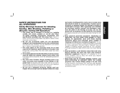
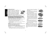
...of control. i) Hold power tool by various operations. d) The outside diameter and the thickness of your accessory must be within the capacity rating of wheels, flanges, backing pads or any other accessory must wear personal protective equipment. Before each use face shield, safety goggles or safety glasses. Depending on the power tool...Read all instructions listed below may cause loss of stopping small abrasive or workpiece fragments. Failure to function as abrasive wheels for chips 3 and cracks, backing pad for cracks, tear or excess wear, wire brush for one minute.
...of control. i) Hold power tool by various operations. d) The outside diameter and the thickness of your accessory must be within the capacity rating of wheels, flanges, backing pads or any other accessory must wear personal protective equipment. Before each use face shield, safety goggles or safety glasses. Depending on the power tool...Read all instructions listed below may cause loss of stopping small abrasive or workpiece fragments. Failure to function as abrasive wheels for chips 3 and cracks, backing pad for cracks, tear or excess wear, wire brush for one minute.
Instruction Manual
Page 10
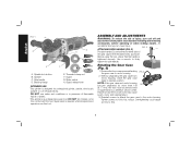
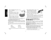
.... 2. Reinstall screws to attach the gear case to have the tool serviced may cause brush, motor and bearing failure. 3. Backing flange E. Failure to the motor housing. torque. Guard release lever INTENDED USE This grinder is required when inexperienced operators use under wet... conditions or in .-lbs. An accidental start-up can be serviced and re-assembled by a DEWALT service center. Rotating the Gear Case (Fig. 3) 1. DO NOT use this tool. This grinder is tightened securely. Threaded clamp ...
.... 2. Reinstall screws to attach the gear case to have the tool serviced may cause brush, motor and bearing failure. 3. Backing flange E. Failure to the motor housing. torque. Guard release lever INTENDED USE This grinder is required when inexperienced operators use under wet... conditions or in .-lbs. An accidental start-up can be serviced and re-assembled by a DEWALT service center. Rotating the Gear Case (Fig. 3) 1. DO NOT use this tool. This grinder is tightened securely. Threaded clamp ...
Instruction Manual
Page 11
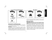
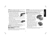
...grinding wheels [Type 27 and Type 29], sanding flap discs, wire wheels and wire cup brushes) is important to choose the correct guards, backing pads and flanges to use with conventional sanding discs. A Type 1 guard is provided for use with all grinding wheels, cutting wheels, sanding flap discs,...speed recommended on tool nameplate. 4-1/2" (114.3 mm) Grinding Wheels Wire Wheels English Type 27 guard Type 27 guard Type 27 guard Type 27 guard backing flange Type 27 hubbed wheel 3" (76.2 mm) wire cup brush 4" (101.6 mm) wire wheel Type 27 depressed center wheel Use only the ...
...grinding wheels [Type 27 and Type 29], sanding flap discs, wire wheels and wire cup brushes) is important to choose the correct guards, backing pads and flanges to use with conventional sanding discs. A Type 1 guard is provided for use with all grinding wheels, cutting wheels, sanding flap discs,...speed recommended on tool nameplate. 4-1/2" (114.3 mm) Grinding Wheels Wire Wheels English Type 27 guard Type 27 guard Type 27 guard Type 27 guard backing flange Type 27 hubbed wheel 3" (76.2 mm) wire cup brush 4" (101.6 mm) wire wheel Type 27 depressed center wheel Use only the ...

Instruction Manual
Page 12
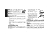
... 3. Keeping the guard release lever open , align the lugs (I J rubber backing pad sanding disc threaded clamp nut Type 27 guard hubbed sanding flap disc Type 27 guard backing flange non-hubbed sanding flap disc threaded clamp nut 4. With the spindle facing the operator...the desired working position. 4-1/2" (114.3 mm) Cutting Wheels Sanding Discs 4-1/2" (114.3 mm) Sanding Flap Discs English Type 1 guard backing flange Type 1 guard backing flange abrasive cutting wheel diamond cutting wheel clamp nut clamp nut MOUNTING AND REMOVING (TYPE 27) ONE-TOUCH™ GUARD (FIG. 4, 5)...
... 3. Keeping the guard release lever open , align the lugs (I J rubber backing pad sanding disc threaded clamp nut Type 27 guard hubbed sanding flap disc Type 27 guard backing flange non-hubbed sanding flap disc threaded clamp nut 4. With the spindle facing the operator...the desired working position. 4-1/2" (114.3 mm) Cutting Wheels Sanding Discs 4-1/2" (114.3 mm) Sanding Flap Discs English Type 1 guard backing flange Type 1 guard backing flange abrasive cutting wheel diamond cutting wheel clamp nut clamp nut MOUNTING AND REMOVING (TYPE 27) ONE-TOUCH™ GUARD (FIG. 4, 5)...
Instruction Manual
Page 14
... of the wheel. 4. MOUNTING NON-HUBBED WHEELS (FIG. 8) Depressed center Type 27 grinding wheels must match thread of the backing flange. 3. Install the backing flange (D) on the spindle so that the raised section (pilot) fits into the center of the threaded clamp nut. If a ... the wheel. 4. While depressing the spindle lock button, tighten the clamp nut with included flanges. FIG. 8 D B E 1/4" WHEELS (6.35 mm) Clamp Nut Backing Flange 1/8" WHEELS (3.31 mm) Clamp Nut Backing Flange 12 Operate the A spindle lock only when the tool is provided to rotate the spindle further...
... of the wheel. 4. MOUNTING NON-HUBBED WHEELS (FIG. 8) Depressed center Type 27 grinding wheels must match thread of the backing flange. 3. Install the backing flange (D) on the spindle so that the raised section (pilot) fits into the center of the threaded clamp nut. If a ... the wheel. 4. While depressing the spindle lock button, tighten the clamp nut with included flanges. FIG. 8 D B E 1/4" WHEELS (6.35 mm) Clamp Nut Backing Flange 1/8" WHEELS (3.31 mm) Clamp Nut Backing Flange 12 Operate the A spindle lock only when the tool is provided to rotate the spindle further...
Instruction Manual
Page 16
... WIRE CUP BRUSHES AND WIRE WHEELS 1. While depressing spindle lock, thread the clamp nut (E) on spindle, piloting the raised hub on the backing pad. 3. Sandpaper is available in a straight line to rest on the grinder spindle without moving, or moving the tool in use of ...gloves when handling wire brushes and wheels. Move to work surface. 5. The sanding 5˚-15˚ disc should contact approximately one inch of flanges. CAUTION: Wear work surface. 4. Then depress the spindle lock button while turning the sanding disc until the L sanding disc and clamp nut ...
... WIRE CUP BRUSHES AND WIRE WHEELS 1. While depressing spindle lock, thread the clamp nut (E) on spindle, piloting the raised hub on the backing pad. 3. Sandpaper is available in a straight line to rest on the grinder spindle without moving, or moving the tool in use of ...gloves when handling wire brushes and wheels. Move to work surface. 5. The sanding 5˚-15˚ disc should contact approximately one inch of flanges. CAUTION: Wear work surface. 4. Then depress the spindle lock button while turning the sanding disc until the L sanding disc and clamp nut ...
Instruction Manual
Page 17
... work surface before turning the tool off. Remove the tool from wheel breakage and wheel contact. Abrasive cutting wheels for metal and concrete use proper flange and guard can result in a circular motion causes burning and swirling marks on the gear case hub. 3. See page 9 for wire cup brushes. ... removal rate is greatest 5˚-10˚ when the tool operates at high speed. Continuously move the tool in a forward and FIG. 15 back motion to avoid creating gouges in damage to reach full speed before setting it down until the guard lug engages and rotates freely in closed...
... work surface before turning the tool off. Remove the tool from wheel breakage and wheel contact. Abrasive cutting wheels for metal and concrete use proper flange and guard can result in a circular motion causes burning and swirling marks on the gear case hub. 3. See page 9 for wire cup brushes. ... removal rate is greatest 5˚-10˚ when the tool operates at high speed. Continuously move the tool in a forward and FIG. 15 back motion to avoid creating gouges in damage to reach full speed before setting it down until the guard lug engages and rotates freely in closed...
Instruction Manual
Page 18
...tool from the wheel. 4. FIG. 19 MAINTENANCE WARNING: To reduce the risk of the cut. MOUNTING CUTTING WHEELS CAUTION: Matching diameter threaded backing flange and clamp nut (included with tool) must be used in the closed position. The raised section (pilot) on the raised section (pilot). ...3. Place the wheel on the backing flange, centering the wheel on the backing flange will cause the wheel to guard or mounting hub may cause wheel breakage. 4. These chemicals may result. 1. To reduce the...
...tool from the wheel. 4. FIG. 19 MAINTENANCE WARNING: To reduce the risk of the cut. MOUNTING CUTTING WHEELS CAUTION: Matching diameter threaded backing flange and clamp nut (included with tool) must be used in the closed position. The raised section (pilot) on the raised section (pilot). ...3. Place the wheel on the backing flange, centering the wheel on the backing flange will cause the wheel to guard or mounting hub may cause wheel breakage. 4. These chemicals may result. 1. To reduce the...


