
Instruction Manual
Page 3
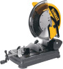
...REMOVE ADJUSTING KEYS AND WRENCHES. Form habit of electric shock, this equipment has a polarized plug (one blade is in a polarized outlet, only one way. All visitors should be sure 1 392736-01,00,DW872 6/29/00 9:00 AM Page 1 English IF YOU HAVE ANY QUESTIONS OR COMMENTS ABOUT THIS OR ANY... DEWALT TOOL, CALL US TOLL FREE AT: 1-800-4-DEWALT (1-800-433-9258) CARRY HANDLE LOCK DOWN PIN TRIGGER SWITCH BLADE LOCK LEVER AUTORETRACTING GUARD BLADE VISE VISE LEVER BASE ...
...REMOVE ADJUSTING KEYS AND WRENCHES. Form habit of electric shock, this equipment has a polarized plug (one blade is in a polarized outlet, only one way. All visitors should be sure 1 392736-01,00,DW872 6/29/00 9:00 AM Page 1 English IF YOU HAVE ANY QUESTIONS OR COMMENTS ABOUT THIS OR ANY... DEWALT TOOL, CALL US TOLL FREE AT: 1-800-4-DEWALT (1-800-433-9258) CARRY HANDLE LOCK DOWN PIN TRIGGER SWITCH BLADE LOCK LEVER AUTORETRACTING GUARD BLADE VISE VISE LEVER BASE ...

Instruction Manual
Page 4
...saw without guards in line voltage resulting accessories may affect its intended function - Consult the instruction Additional Specific Safety Rules • BE SURE THE BLADE BOLT IS TIGHTENED SECURELY BEFORE CUTTING. • Wear eye protection. • Keep hands out of path of power and overheating. The smaller ...vertical clamp and/or a vise to stop . • REPLACEMENT PARTS. Make sure switch is in doubt, use one way. 392736-01,00,DW872 6/29/00 9:00 AM Page 2 English to use the next heavier gage. If in off tool and wait for recommended accessories. If the ...
...saw without guards in line voltage resulting accessories may affect its intended function - Consult the instruction Additional Specific Safety Rules • BE SURE THE BLADE BOLT IS TIGHTENED SECURELY BEFORE CUTTING. • Wear eye protection. • Keep hands out of path of power and overheating. The smaller ...vertical clamp and/or a vise to stop . • REPLACEMENT PARTS. Make sure switch is in doubt, use one way. 392736-01,00,DW872 6/29/00 9:00 AM Page 2 English to use the next heavier gage. If in off tool and wait for recommended accessories. If the ...

Instruction Manual
Page 5
... electric tool. Power Supply Be sure your power supply agrees with the blade. 392736-01,00,DW872 6/29/00 9:00 AM Page 3 English • Do not use abrasive cut off ...wheels or other type of saw blade. • Do not cut . If a crack or flaw is turned on the upstroke of the blade...DO NOT CUT ELECTRICALLY LIVE MATERIAL. • Use only genuine DEWALT14" (355mm) carbide tipped metal cutting blades. The auxiliary vertical clamp must be sharp and hot. To reduce your tool periodically following the procedure in...
... electric tool. Power Supply Be sure your power supply agrees with the blade. 392736-01,00,DW872 6/29/00 9:00 AM Page 3 English • Do not use abrasive cut off ...wheels or other type of saw blade. • Do not cut . If a crack or flaw is turned on the upstroke of the blade...DO NOT CUT ELECTRICALLY LIVE MATERIAL. • Use only genuine DEWALT14" (355mm) carbide tipped metal cutting blades. The auxiliary vertical clamp must be sharp and hot. To reduce your tool periodically following the procedure in...
Instruction Manual
Page 6
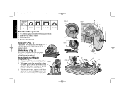
... in the inner clamp washer (H). With motor arm in the up position, rotate the lower guard (A) out of the way and A hold with one of Blade (Fig. 3 & 4) 1. With FIG. 3 A B B FIG. 5 A FIG. 6 E G 4 FIG. 4 A F E D C I ) until it engages one hand. (Shown in dotted ...(A) out. With the same hand, depress the blade lock lever (I H G D F A C B Motor arm will then pivot upward. 392736-01,00,DW872 6/29/00 9:00 AM Page 4 English 5-3/16" 4-3/4" 4-1/4 x 7" 5-9/16" Standard Equipment 1 14" (355mm) genuine DEWALT Metal Cutting Blade. 1 Blade Wrench in base holder. 1 Vise Attachment 1 ...
... in the inner clamp washer (H). With motor arm in the up position, rotate the lower guard (A) out of the way and A hold with one of Blade (Fig. 3 & 4) 1. With FIG. 3 A B B FIG. 5 A FIG. 6 E G 4 FIG. 4 A F E D C I ) until it engages one hand. (Shown in dotted ...(A) out. With the same hand, depress the blade lock lever (I H G D F A C B Motor arm will then pivot upward. 392736-01,00,DW872 6/29/00 9:00 AM Page 4 English 5-3/16" 4-3/4" 4-1/4 x 7" 5-9/16" Standard Equipment 1 14" (355mm) genuine DEWALT Metal Cutting Blade. 1 Blade Wrench in base holder. 1 Vise Attachment 1 ...

Instruction Manual
Page 7
...as it approaches the material and is exposed as shown against the inner clamp washer (H). WARNING: VISUALLY CHECK BLADE FOR CRACKS OR OTHER DAMAGE. WARNING: BE SURE THE BLADE BOLT IS TIGHTENED SECURELY AND THE BOLT COVER IS COVERING THE BOLT HEAD BEFORE CUTTING. To accomplish this, rotate... the outer clamp washer, flat washer, lock washer and bolt hand tight. 5. IF BLADE IS DAMAGED IN ANY WAY, HAVE IT RECONDITIONED AT A QUALIFIED SAW BLADE SERVICE SHOP. 392736-01,00,DW872 6/29/00 9:00 AM Page 5 FIG. 7 D B E C A FIG. 8 A FIG. 9 A B the hex wrench rotate the bolt cover (B) ...
...as it approaches the material and is exposed as shown against the inner clamp washer (H). WARNING: VISUALLY CHECK BLADE FOR CRACKS OR OTHER DAMAGE. WARNING: BE SURE THE BLADE BOLT IS TIGHTENED SECURELY AND THE BOLT COVER IS COVERING THE BOLT HEAD BEFORE CUTTING. To accomplish this, rotate... the outer clamp washer, flat washer, lock washer and bolt hand tight. 5. IF BLADE IS DAMAGED IN ANY WAY, HAVE IT RECONDITIONED AT A QUALIFIED SAW BLADE SERVICE SHOP. 392736-01,00,DW872 6/29/00 9:00 AM Page 5 FIG. 7 D B E C A FIG. 8 A FIG. 9 A B the hex wrench rotate the bolt cover (B) ...

Instruction Manual
Page 9
...Clamping Tips (Fig. 10, 11, 12) • TURN OFF AND UNPLUG TOOL BEFORE MAKING ANY ADJUSTMENT TO THE SAW OR REPOSITIONING A WORKPIECE. blade extends into a collection bin, loosen the screw (A), adjust the chip deflector (B) angle and retighten the screw. Loosen the two angle plate screws ... will drop into the corresponding hole (F) in selecting and placing these 7 392736-01,00,DW872 6/29/00 9:00 AM Page 7 English FIG. 13 FIG. 14 FIG. 15 the clamp. Place a square (C) against the blade (D), adjust the fence against the square and then re-lock the fence. 4. Slots (C)...
...Clamping Tips (Fig. 10, 11, 12) • TURN OFF AND UNPLUG TOOL BEFORE MAKING ANY ADJUSTMENT TO THE SAW OR REPOSITIONING A WORKPIECE. blade extends into a collection bin, loosen the screw (A), adjust the chip deflector (B) angle and retighten the screw. Loosen the two angle plate screws ... will drop into the corresponding hole (F) in selecting and placing these 7 392736-01,00,DW872 6/29/00 9:00 AM Page 7 English FIG. 13 FIG. 14 FIG. 15 the clamp. Place a square (C) against the blade (D), adjust the fence against the square and then re-lock the fence. 4. Slots (C)...

Instruction Manual
Page 10
...full speed. 3. Material must be made , increase feed rate, allowing the blade to reduce vibration. Drill four holes 5/16" through the smallest cross section. • Avoid cutting large, flat, horizontal surfaces where possible. 392736-01,00,DW872 6/29/00 9:00 AM Page 8 English FIG. 16 C B D ...FIG. 17 workpiece. Once contact is complete. 4. A .3" (8 MM) clamps. Make a dry run before the cut . • The ringing sound of the blade and the tool: • Position the ...
...full speed. 3. Material must be made , increase feed rate, allowing the blade to reduce vibration. Drill four holes 5/16" through the smallest cross section. • Avoid cutting large, flat, horizontal surfaces where possible. 392736-01,00,DW872 6/29/00 9:00 AM Page 8 English FIG. 16 C B D ...FIG. 17 workpiece. Once contact is complete. 4. A .3" (8 MM) clamps. Make a dry run before the cut . • The ringing sound of the blade and the tool: • Position the ...

Instruction Manual
Page 11
... 2 oz. (60 grams) of your local dealer or authorized service center. 392736-01,00,DW872 6/29/00 9:00 AM Page 9 English 2. Insert 1/4-20 screws down to 90 days, depending upon use with the performance of DEWALT Lubricant Part No. 790206 (6 oz. Brushes should be relubricated every 60 to .3" (8mm) ...from date of the mounting surface plus 4 inches. To inspect brushes, unscrew the two end cap screws (A) and remove end cap (B). Accessories Blades are warranted for wear. Cleaning Blowing dust and grit out of the main housing and chip deflector by means of an air hose is seen...
... 2 oz. (60 grams) of your local dealer or authorized service center. 392736-01,00,DW872 6/29/00 9:00 AM Page 9 English 2. Insert 1/4-20 screws down to 90 days, depending upon use with the performance of DEWALT Lubricant Part No. 790206 (6 oz. Brushes should be relubricated every 60 to .3" (8mm) ...from date of the mounting surface plus 4 inches. To inspect brushes, unscrew the two end cap screws (A) and remove end cap (B). Accessories Blades are warranted for wear. Cleaning Blowing dust and grit out of the main housing and chip deflector by means of an air hose is seen...

Instruction Manual
Page 12
...See Fence Operation on page 2. 2.Contact your electric company. 3.Check generator output voltage. WHAT TO DO... 1.Check for Permanent Mounting. 2.Replace blade. 3.Refer to stand or work . 4.Clamp workpiece securely. Fence slipping or workpiece incorrectly placed or clamped. 2. Low generator voltage. Check for... Workpiece incorrectly placed or clamped. Trouble Shooting Guide WHAT TO DO... 1.Plug in saw blade. 3. Make sure material is engaged. Blade is not square to make cut. 4. 392736-01,00,DW872 6/29/00 9:00 AM Page 10 English TROUBLE! TROUBLE! Fence not adjusted correctly....
...See Fence Operation on page 2. 2.Contact your electric company. 3.Check generator output voltage. WHAT TO DO... 1.Check for Permanent Mounting. 2.Replace blade. 3.Refer to stand or work . 4.Clamp workpiece securely. Fence slipping or workpiece incorrectly placed or clamped. 2. Low generator voltage. Check for... Workpiece incorrectly placed or clamped. Trouble Shooting Guide WHAT TO DO... 1.Plug in saw blade. 3. Make sure material is engaged. Blade is not square to make cut. 4. 392736-01,00,DW872 6/29/00 9:00 AM Page 10 English TROUBLE! TROUBLE! Fence not adjusted correctly....

Parts Diagram
Page 2
Page 1 Please visit www.dewaltservicenet.com for DW872 Type 2 Description Qty Required SCREW,TAPTITE 4 SCREW 2 SCREW,M4X19 4 SCREW 7 SCREW,PLASTITE 3 SCREW 4 SCREW 2 SCREW 6 SCREW 2 SCREW 2 FIELD 1 ARMATURE 1 FIELD CASE 1 END CAP 1 FAN BAFFLE 1 ... RING ASM 1 ARM/GEAR CASE 1 BEARING,BALL 1 BALL BEARING 2 GEAR CASE COVER ASSY. 1 UPPER GUARD 1 LOWER GUARD 1 INNER CL.WASHER 1 OUT CLMP WASHER 1 SCREW 1 WASHER 1 BLADE LOCK PIN 1 COPYRIGHT© 2005. Item Number 1 2 3 4 5 6 7 8 9 10 11 12 13 14 15 16 17 18 19 21 22 23 24 25 26 27 28...
Page 1 Please visit www.dewaltservicenet.com for DW872 Type 2 Description Qty Required SCREW,TAPTITE 4 SCREW 2 SCREW,M4X19 4 SCREW 7 SCREW,PLASTITE 3 SCREW 4 SCREW 2 SCREW 6 SCREW 2 SCREW 2 FIELD 1 ARMATURE 1 FIELD CASE 1 END CAP 1 FAN BAFFLE 1 ... RING ASM 1 ARM/GEAR CASE 1 BEARING,BALL 1 BALL BEARING 2 GEAR CASE COVER ASSY. 1 UPPER GUARD 1 LOWER GUARD 1 INNER CL.WASHER 1 OUT CLMP WASHER 1 SCREW 1 WASHER 1 BLADE LOCK PIN 1 COPYRIGHT© 2005. Item Number 1 2 3 4 5 6 7 8 9 10 11 12 13 14 15 16 17 18 19 21 22 23 24 25 26 27 28...
Parts Diagram
Page 6
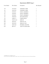
All Rights Reserved. Please visit www.dewaltservicenet.com for DW872 Type 2 Description Qty Required WARNING LABEL 1 WARNING LABEL 2 FENCE ASSEMBLY 1 FENCE ASSEMBLY 1 FENCE ASSEMBLY 1 RETAINING RING 1 SCREW,M5X20 1 GREASE 1 GREASE,1 LB. 1 GREASE, 7LBS 1 BUSHING ADAPTER 1 14IN 70T SAW BLADE 1 COPYRIGHT© 2005. Parts list, pricing, and availability subject to change. Page 5 Item Number...
All Rights Reserved. Please visit www.dewaltservicenet.com for DW872 Type 2 Description Qty Required WARNING LABEL 1 WARNING LABEL 2 FENCE ASSEMBLY 1 FENCE ASSEMBLY 1 FENCE ASSEMBLY 1 RETAINING RING 1 SCREW,M5X20 1 GREASE 1 GREASE,1 LB. 1 GREASE, 7LBS 1 BUSHING ADAPTER 1 14IN 70T SAW BLADE 1 COPYRIGHT© 2005. Parts list, pricing, and availability subject to change. Page 5 Item Number...


