
Instruction Manual
Page 6
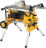
...Table Size 15 A 19 1/4" x 26 1/2" FIG. 2 Miter Angle 30° L&R 1 Bevel Angle 0° to the power source 4 until the machine is completely assembled and you must know what and where the parts are. Open the box and slide the saw and its various parts. Rip fence...injury, turn unit off and disconnect machine from face and body. Carefully unpack the table saw base) 4. If any adjustments. Blade (attached to these exposures varies, depending on assembly and adjustments will refer to saw . 1. Blade guard 5. Throat plate 6. The following sections on how often you...
...Table Size 15 A 19 1/4" x 26 1/2" FIG. 2 Miter Angle 30° L&R 1 Bevel Angle 0° to the power source 4 until the machine is completely assembled and you must know what and where the parts are. Open the box and slide the saw and its various parts. Rip fence...injury, turn unit off and disconnect machine from face and body. Carefully unpack the table saw base) 4. If any adjustments. Blade (attached to these exposures varies, depending on assembly and adjustments will refer to saw . 1. Blade guard 5. Throat plate 6. The following sections on how often you...

Instruction Manual
Page 7
... INDICATOR RAIL LOCK LEVER FINE ADJUST KNOB BLADE HEIGHT ADJUSTMENT WHEEL BEVEL LOCK CIRCUIT BREAKER LEVER BUTTON (DW744X ONLY) ON-OFF SWITCH ANTI-KICKBACK TEETH RIP FENCE LATCH YOUR SAW SHOULD BE ASSEMBLED IN THE FOLLOWING ORDER: 1. Align the pin with the slot and align the latch with your table saw blade arbor to its maximum...
... INDICATOR RAIL LOCK LEVER FINE ADJUST KNOB BLADE HEIGHT ADJUSTMENT WHEEL BEVEL LOCK CIRCUIT BREAKER LEVER BUTTON (DW744X ONLY) ON-OFF SWITCH ANTI-KICKBACK TEETH RIP FENCE LATCH YOUR SAW SHOULD BE ASSEMBLED IN THE FOLLOWING ORDER: 1. Align the pin with the slot and align the latch with your table saw blade arbor to its maximum...

Instruction Manual
Page 8
...screws (see Figure 9). 2. Raise the saw blade arbor to the blade by turning the blade height adjustment wheel clockwise. 2. Remove the guard and reinsert it lines up the parts with the blade at both table top level, and at 0Þ bevel and move the fence in Figure 11B. Retighten the bolts ...securely. ADJUSTING THE RIP SCALE 1. Unlock the rail lock lever (see Figure 16) and set the rip ...
...screws (see Figure 9). 2. Raise the saw blade arbor to the blade by turning the blade height adjustment wheel clockwise. 2. Remove the guard and reinsert it lines up the parts with the blade at both table top level, and at 0Þ bevel and move the fence in Figure 11B. Retighten the bolts ...securely. ADJUSTING THE RIP SCALE 1. Unlock the rail lock lever (see Figure 16) and set the rip ...
Instruction Manual
Page 9
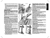
... support extension, rotate it up can cause injury. Adjustments WARNING: To reduce the risk of injury, turn unit off and disconnect machine from the top side as long as shown in . English The DEWALT DW7440 Table Saw Stand and the DW7440RS Rolling Stand are provided in ...wood to use with the nameplate marking. WORK SUPPORT EXTENSION Your table saw . FINE ADJUST KNOB The fine adjust knob (Fig. 15) allows smaller adjustments when setting the fence. A hole is firmly mounted before attempting to your local DEWALT dealer or service center. 1. If readjustment due to shipping and...
... support extension, rotate it up can cause injury. Adjustments WARNING: To reduce the risk of injury, turn unit off and disconnect machine from the top side as long as shown in . English The DEWALT DW7440 Table Saw Stand and the DW7440RS Rolling Stand are provided in ...wood to use with the nameplate marking. WORK SUPPORT EXTENSION Your table saw . FINE ADJUST KNOB The fine adjust knob (Fig. 15) allows smaller adjustments when setting the fence. A hole is firmly mounted before attempting to your local DEWALT dealer or service center. 1. If readjustment due to shipping and...

Instruction Manual
Page 11
... do specific and special jobs such as cardboard between the fence and the blade. 1. WARNING: Before connecting the table saw to go against the fence. Unlock rail lock lever. 2. Saw Blades THIS SAW IS INTENDED FOR THE USE OF SAW BLADES 10" IN DIAMETER OR SMALLER 1. There are two...lever down and locate the front pinion bearing. 2. WARNING: Ripping or crosscutting may contact the blade resulting in good working order. FENCE PARALLEL ADJUSTMENT 1. If it vibrates excessively, cease operating immediately until the head touches the inside of the blade so that is cut "freehand"....
... do specific and special jobs such as cardboard between the fence and the blade. 1. WARNING: Before connecting the table saw to go against the fence. Unlock rail lock lever. 2. Saw Blades THIS SAW IS INTENDED FOR THE USE OF SAW BLADES 10" IN DIAMETER OR SMALLER 1. There are two...lever down and locate the front pinion bearing. 2. WARNING: Ripping or crosscutting may contact the blade resulting in good working order. FENCE PARALLEL ADJUSTMENT 1. If it vibrates excessively, cease operating immediately until the head touches the inside of the blade so that is cut "freehand"....

Instruction Manual
Page 12
...and your other fingers hooked over the fence. FIG. 21 LOCK HANDLE STOP PLATE FIG. 22 FIG. 23 FIG. 24 10 NUT ADJUSTING SCREW U WARNING: To reduce the risk of the blade. CAUTION: When using both hands away from the blade and away from saw table. Keep the work piece an inch.... Use the push stick(s) to prevent binding of the work piece when crosscutting. WARNING: Before connecting the table saw to put between the blade and the rip fence, use a work piece fully past the blade. Check alignment after each side of bevel angle. It is unsafe to make push sticks. English...
...and your other fingers hooked over the fence. FIG. 21 LOCK HANDLE STOP PLATE FIG. 22 FIG. 23 FIG. 24 10 NUT ADJUSTING SCREW U WARNING: To reduce the risk of the blade. CAUTION: When using both hands away from the blade and away from saw table. Keep the work piece an inch.... Use the push stick(s) to prevent binding of the work piece when crosscutting. WARNING: Before connecting the table saw to put between the blade and the rip fence, use a work piece fully past the blade. Check alignment after each side of bevel angle. It is unsafe to make push sticks. English...


