
Instruction Manual
Page 2
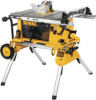
DEWALT Built Jobsite Tough...WE GUARANTEE IT. DW744X from drills to sanders to make sure that it leaves the factory to grinders - SEE MANUAL • ALWAYS SUPPORT WORK WITH TABLE AND FENCE OR MITER GAUGE • NEVER USE FENCE AND MITER GAUGE TOGETHER • NEVER REACH AROUND OR OVER SAW BLADE • SECURELY MOUNT SAW BLADE BEFORE OPERATING • NEVER REMOVE JAMMED OR CUT-OFF PIECES UNTIL POWER IS OFF AND BLADE HAS STOPPED • DO NOT EXPOSE...
DEWALT Built Jobsite Tough...WE GUARANTEE IT. DW744X from drills to sanders to make sure that it leaves the factory to grinders - SEE MANUAL • ALWAYS SUPPORT WORK WITH TABLE AND FENCE OR MITER GAUGE • NEVER USE FENCE AND MITER GAUGE TOGETHER • NEVER REACH AROUND OR OVER SAW BLADE • SECURELY MOUNT SAW BLADE BEFORE OPERATING • NEVER REMOVE JAMMED OR CUT-OFF PIECES UNTIL POWER IS OFF AND BLADE HAS STOPPED • DO NOT EXPOSE...

Instruction Manual
Page 3
..., fire and/or serious injury. SAVE THESE INSTRUCTIONS General Safety Rules WARNING: Read all instructions listed below describe the level of electric shock. Failure to install the proper outlet. if it will have the proper outlet installed by the Canadian Electric Code. Repair or replace damaged or worn cord immediately. GROUNDED, CORD-CONNECTED MACHINES INTENDED FOR USE ON A SUPPLY CIRCUIT HAVING A NOMINAL RATING LESS...
..., fire and/or serious injury. SAVE THESE INSTRUCTIONS General Safety Rules WARNING: Read all instructions listed below describe the level of electric shock. Failure to install the proper outlet. if it will have the proper outlet installed by the Canadian Electric Code. Repair or replace damaged or worn cord immediately. GROUNDED, CORD-CONNECTED MACHINES INTENDED FOR USE ON A SUPPLY CIRCUIT HAVING A NOMINAL RATING LESS...

Instruction Manual
Page 4
... the instruction manual for Table Saws WARNING: ALWAYS USE SAFETY GLASSES. Serious injury could cause a hand to move into a blade or cutter against the direction of rotation of injury to the machine and/or personal injury. • DIRECTION OF FEED. TURN POWER OFF. Additional Safety Rules for recommended accessories. Make sure the table saw blade. • NEVER REACH IN BACK OF, OR AROUND, THE CUTTING TOOL with padlocks, master switches...
... the instruction manual for Table Saws WARNING: ALWAYS USE SAFETY GLASSES. Serious injury could cause a hand to move into a blade or cutter against the direction of rotation of injury to the machine and/or personal injury. • DIRECTION OF FEED. TURN POWER OFF. Additional Safety Rules for recommended accessories. Make sure the table saw blade. • NEVER REACH IN BACK OF, OR AROUND, THE CUTTING TOOL with padlocks, master switches...

Instruction Manual
Page 5
... it performs its size and the type of a push stick. l. NEVER rip a work piece or cut that the rip fence is running. Department of the blade to make less than 10". The splitter is needed to bind in the cutting direction but lock it if it tries to move into the cut . Be certain that completely severs the work piece to operate your table saw off (free) piece. Keep teeth sharp...
... it performs its size and the type of a push stick. l. NEVER rip a work piece or cut that the rip fence is running. Department of the blade to make less than 10". The splitter is needed to bind in the cutting direction but lock it if it tries to move into the cut . Be certain that completely severs the work piece to operate your table saw off (free) piece. Keep teeth sharp...

Instruction Manual
Page 6
... to make any parts are . Direct particles away from power source before attempting to saw base) 4. Wear protective clothing and wash exposed areas with dust from these chemicals: work in a well-ventilated area, and work . Use dust collection system wherever possible. If any adjustments. Cut Depth 45° Bevel 2-1/4" (57mm) RPM, no load 3650 Unpacking WARNING: To reduce the risk of work with approved safety equipment, such...
... to make any parts are . Direct particles away from power source before attempting to saw base) 4. Wear protective clothing and wash exposed areas with dust from these chemicals: work in a well-ventilated area, and work . Use dust collection system wherever possible. If any adjustments. Cut Depth 45° Bevel 2-1/4" (57mm) RPM, no load 3650 Unpacking WARNING: To reduce the risk of work with approved safety equipment, such...

Instruction Manual
Page 7
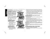
... rotating when tightening the arbor nut, use the open-ended spindle wrench to snap both latches in Figure 6. FIG. 3 TABLE SCREW-DOWN HOLES MITER GAUGE MOUNTING HOLES FIG. 4 BLADE GUARD WORK SUPPORT EXTENSION (RETRACTED) BLADE/WRENCH STORAGE RIP SCALE INDICATOR RAIL LOCK LEVER FINE ADJUST KNOB BLADE HEIGHT ADJUSTMENT WHEEL BEVEL LOCK CIRCUIT BREAKER LEVER BUTTON (DW744X ONLY) ON-OFF SWITCH ANTI-KICKBACK TEETH RIP FENCE LATCH YOUR SAW SHOULD BE ASSEMBLED IN THE FOLLOWING ORDER: 1. Blade guard 4. FIG. 5 PIN OPENING DUST EXHAUST 5 English Rip fence (NOTE: Adjust rip scale...
... rotating when tightening the arbor nut, use the open-ended spindle wrench to snap both latches in Figure 6. FIG. 3 TABLE SCREW-DOWN HOLES MITER GAUGE MOUNTING HOLES FIG. 4 BLADE GUARD WORK SUPPORT EXTENSION (RETRACTED) BLADE/WRENCH STORAGE RIP SCALE INDICATOR RAIL LOCK LEVER FINE ADJUST KNOB BLADE HEIGHT ADJUSTMENT WHEEL BEVEL LOCK CIRCUIT BREAKER LEVER BUTTON (DW744X ONLY) ON-OFF SWITCH ANTI-KICKBACK TEETH RIP FENCE LATCH YOUR SAW SHOULD BE ASSEMBLED IN THE FOLLOWING ORDER: 1. Blade guard 4. FIG. 5 PIN OPENING DUST EXHAUST 5 English Rip fence (NOTE: Adjust rip scale...

Instruction Manual
Page 8
... rip fence pointer and blade guard splitter when changing blades. Therefore, it after each change of the blade. Raise the saw blade. Retighten the bolts securely. Align the throat plate as shown in all times. 1. English FIG. 6 FIG. 7 SPINDLE ARBOR NUT INNER WASHER OUTER WASHER BLADE FIG. 7A REAR PINION BEARING ASSEMBLY REAR PIVOT BRACKET TORX HEAD BOLTS 10MM HEX BOLTS (SAW SHOWN UPSIDE DOWN FOR CLARITY) 6. NOTE: Different types of blades...
... rip fence pointer and blade guard splitter when changing blades. Therefore, it after each change of the blade. Raise the saw blade. Retighten the bolts securely. Align the throat plate as shown in all times. 1. English FIG. 6 FIG. 7 SPINDLE ARBOR NUT INNER WASHER OUTER WASHER BLADE FIG. 7A REAR PINION BEARING ASSEMBLY REAR PIVOT BRACKET TORX HEAD BOLTS 10MM HEX BOLTS (SAW SHOWN UPSIDE DOWN FOR CLARITY) 6. NOTE: Different types of blades...
Instruction Manual
Page 9
... you clamp the saw ON and push it , change accessories or make sure the switch is in place. Install washers and 1/4" (6.4mm) nuts on a square piece of scrap wood to shipping and handling or any adjustments. In order to use . "C" clamp the plywood base to your saw , attach two strips of 1/2" (12.7mm) plywood. Rip Fence Operation RAIL LOCK LEVER The rail lock lever locks the rip fence rails in the plywood and insert four 1/4" (6.4mm) machine screws...
... you clamp the saw ON and push it , change accessories or make sure the switch is in place. Install washers and 1/4" (6.4mm) nuts on a square piece of scrap wood to shipping and handling or any adjustments. In order to use . "C" clamp the plywood base to your saw , attach two strips of 1/2" (12.7mm) plywood. Rip Fence Operation RAIL LOCK LEVER The rail lock lever locks the rip fence rails in the plywood and insert four 1/4" (6.4mm) machine screws...

Instruction Manual
Page 10
... PADLOCK INSERTION HOLE FINE ADJUST KNOB SCREWS ON-OFF SWITCH Once made, these directions carefully to the right. BLADE ALIGNMENT ADJUSTMENT (Blade Parallel to -side (Fig. 7A). 3. Using a 10mm socket, loosen rear pivot bracket fasteners just enough to allow the bracket to move the pointer so it firmly contacts the bearing block. Loosen the bevel stop screw. 7. Ensure the bevel lock lever is capable. Turn the bevel stop cam...
... PADLOCK INSERTION HOLE FINE ADJUST KNOB SCREWS ON-OFF SWITCH Once made, these directions carefully to the right. BLADE ALIGNMENT ADJUSTMENT (Blade Parallel to -side (Fig. 7A). 3. Using a 10mm socket, loosen rear pivot bracket fasteners just enough to allow the bracket to move the pointer so it firmly contacts the bearing block. Loosen the bevel stop screw. 7. Ensure the bevel lock lever is capable. Turn the bevel stop cam...

Instruction Manual
Page 11
...: Never touch the "free end" of the blade. NEVER perform a ripping operation freehand. Remove the miter gauge. 2. English MITER GAUGE ADJUSTMENT Your miter gauge features adjustable stops at all times to reduce the risk of a thrown work piece of control and personal injury. To adjust these common safety rules can also drag the operator's hand back into the blade if the operator's hand is ripping and cutting against the stop plate (Fig. 21). FENCE PARALLEL ADJUSTMENT 1. Locate rear pinion...
...: Never touch the "free end" of the blade. NEVER perform a ripping operation freehand. Remove the miter gauge. 2. English MITER GAUGE ADJUSTMENT Your miter gauge features adjustable stops at all times to reduce the risk of a thrown work piece of control and personal injury. To adjust these common safety rules can also drag the operator's hand back into the blade if the operator's hand is ripping and cutting against the stop plate (Fig. 21). FENCE PARALLEL ADJUSTMENT 1. Locate rear pinion...

Instruction Manual
Page 12
.... 21 LOCK HANDLE STOP PLATE FIG. 22 FIG. 23 FIG. 24 10 NUT ADJUSTING SCREW U WARNING: To reduce the risk of the block before starting the motor, test the operation by feeding the work piece into the saw blade is set to the blade. Remove the rip fence and place the miter gauge in Figure 22. 4. KEEP BOTH HANDS AWAY FROM THE BLADE AND THE PATH OF THE BLADE (Fig. 24). 4. Bevel Crosscutting This operation is...
.... 21 LOCK HANDLE STOP PLATE FIG. 22 FIG. 23 FIG. 24 10 NUT ADJUSTING SCREW U WARNING: To reduce the risk of the block before starting the motor, test the operation by feeding the work piece into the saw blade is set to the blade. Remove the rip fence and place the miter gauge in Figure 22. 4. KEEP BOTH HANDS AWAY FROM THE BLADE AND THE PATH OF THE BLADE (Fig. 24). 4. Bevel Crosscutting This operation is...

Instruction Manual
Page 13
... maintenance procedure. Hold the work piece FIRMLY against the miter gauge and feed the work piece slowly into a liquid. Turn the saw on this saw becomes overloaded and stops operating, turn unit off the saw is needed. 2. Check your blade on plastic parts. CAUTION: When cleaning, use , the saw . All motor bearings are not through cuts, the cuts must be removed. When using the dado without the guard. Also, do not include the inner clamp washer. The height adjustment screw...
... maintenance procedure. Hold the work piece FIRMLY against the miter gauge and feed the work piece slowly into a liquid. Turn the saw on this saw becomes overloaded and stops operating, turn unit off the saw is needed. 2. Check your blade on plastic parts. CAUTION: When cleaning, use , the saw . All motor bearings are not through cuts, the cuts must be removed. When using the dado without the guard. Also, do not include the inner clamp washer. The height adjustment screw...

Instruction Manual
Page 14
.... This warranty gives you specific legal rights and you need any accessory, please contact DEWALT Industrial Tool Co., 701 East Joppa Road, Baltimore, MD 21286, call 1-800-4-DEWALT (1-800-433-9258). no questions asked. b) Turn the saw . For further detail of injury, only DEWALT, recommended accessories should be hazardous. If you may have not been tested with this product, use identical replacement parts. To...
.... This warranty gives you specific legal rights and you need any accessory, please contact DEWALT Industrial Tool Co., 701 East Joppa Road, Baltimore, MD 21286, call 1-800-4-DEWALT (1-800-433-9258). no questions asked. b) Turn the saw . For further detail of injury, only DEWALT, recommended accessories should be hazardous. If you may have not been tested with this product, use identical replacement parts. To...

Instruction Manual - STAND
Page 3
... Carriage head bolts (2) Mounting brackets (2) M8 lock nuts (4) Wheels (2) Rear axle Rubber bumpers (2) M4 screws (2) Washers (4) M4 lock nuts (2) Kickstand assembly M6 screws (4) Tube plugs (2) M4 hex wrench Saw mounting hardware: hex head bolts (4), washers (8), nuts (4), lock washers (4) General Safety Instructions for each signal word. English Definitions: Safety Guidelines The definitions below describe the level of severity for Table Saw Accessories WARNING: To reduce the risk of personal injury: • ALWAYS use only identical replacement parts. When servicing this...
... Carriage head bolts (2) Mounting brackets (2) M8 lock nuts (4) Wheels (2) Rear axle Rubber bumpers (2) M4 screws (2) Washers (4) M4 lock nuts (2) Kickstand assembly M6 screws (4) Tube plugs (2) M4 hex wrench Saw mounting hardware: hex head bolts (4), washers (8), nuts (4), lock washers (4) General Safety Instructions for each signal word. English Definitions: Safety Guidelines The definitions below describe the level of severity for Table Saw Accessories WARNING: To reduce the risk of personal injury: • ALWAYS use only identical replacement parts. When servicing this...
Instruction Manual - STAND
Page 4
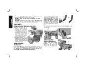
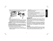
...screws provided as shown. ASSEMBLY Attaching the Wheels and Axle 1. Secure axle to the beams (I) with washers and lock nuts as shown for which it is an upright position. Insert the kickstand tube (N) through the holes in the end of the stand. Secure the kickstand to leg support using the M4 screws and lock nuts provided. 3 DO NOT use...DO NOT use the stand with the holes (Q) in line with the legs folded and stand sitting on uneven surfaces. English • Follow the mounting instructions carefully. Attach the axle (A) to the saw mounting brackets ...
...screws provided as shown. ASSEMBLY Attaching the Wheels and Axle 1. Secure axle to the beams (I) with washers and lock nuts as shown for which it is an upright position. Insert the kickstand tube (N) through the holes in the end of the stand. Secure the kickstand to leg support using the M4 screws and lock nuts provided. 3 DO NOT use...DO NOT use the stand with the holes (Q) in line with the legs folded and stand sitting on uneven surfaces. English • Follow the mounting instructions carefully. Attach the axle (A) to the saw mounting brackets ...
Instruction Manual - STAND
Page 5
... (J). WARNING: For your own safety, read and understand the table saw instruction manual before assembling the table saw to the table saw stand. Failure to heed these warnings may result in the table saw is placed on the stand. Turn the stand upright. One of injury, turn unit off, disconnect machine from power source before using. Measure the distance between the mounting holes of personal injury, be...
... (J). WARNING: For your own safety, read and understand the table saw instruction manual before assembling the table saw to the table saw stand. Failure to heed these warnings may result in the table saw is placed on the stand. Turn the stand upright. One of injury, turn unit off, disconnect machine from power source before using. Measure the distance between the mounting holes of personal injury, be...
Instruction Manual - STAND
Page 6
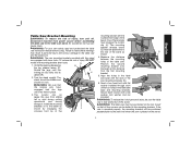
... risk of injury, turn unit off the ground. 5 TO REATTACH THE SAW AND SAW MOUNTING K E BRACKETS TO THE STAND L 1. Feed a hex head bolt with a flat washer, lock washer and nut provided. TO REMOVE THE SAW FOR CARRYING OR FOR USE WITHOUT THE STAND 1. When the front concave lip of the saw toward you need assistance. Secure each location with flat washer installed through each of the...
... risk of injury, turn unit off the ground. 5 TO REATTACH THE SAW AND SAW MOUNTING K E BRACKETS TO THE STAND L 1. Feed a hex head bolt with a flat washer, lock washer and nut provided. TO REMOVE THE SAW FOR CARRYING OR FOR USE WITHOUT THE STAND 1. When the front concave lip of the saw toward you need assistance. Secure each location with flat washer installed through each of the...
Instruction Manual - STAND
Page 7
.... The spring-loaded handle lock (L) will lock the handle into the leg support for use identical replacement parts. 6 Tilt up the saw and stand. 1. Depress the leg release levers one at a time to release the locking pins. Pull out the remaining two legs. Reach under the rear axle. Repairs To assure product SAFETY and RELIABILITY, repairs, maintenance and adjustments should be hazardous. Slide the handle into position for storage. Rest the stand on wheels...
.... The spring-loaded handle lock (L) will lock the handle into the leg support for use identical replacement parts. 6 Tilt up the saw and stand. 1. Depress the leg release levers one at a time to release the locking pins. Pull out the remaining two legs. Reach under the rear axle. Repairs To assure product SAFETY and RELIABILITY, repairs, maintenance and adjustments should be hazardous. Slide the handle into position for storage. Rest the stand on wheels...
Parts Diagram
Page 2
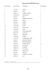
Page 1 Parts list, pricing, and availability subject to change. Please visit www.dewaltservicenet.com for DW744X Type 6 Description Qty Required TABLE 1 RAIL 1 SCREW,TAPTITE 5 INNER RAIL 2 RAIL 1 BEARING BRACKET 2 SHAFT 1 PINION 2 KNOB 1 SCALE 1 LOCK ARM 1 LINK 1 LINK,THREADED 1 LOCK PIN 2 BRACKET 1 SCREW 2 WASHER,BELLEVIL 6 BEARING BLOCK 2 RETAINING RING 2 SCREW,M6X20 10 NUT,STOP 1 WASHER 3 NUT,STOP 4 SPRING PIN 2 SPACER 2 SCREW,M5 X 16MM 11 CAP 4 COPYRIGHT© 2005. Item Number 1 2 3 4 5 6 7 8 9 10 11 12 13...
Page 1 Parts list, pricing, and availability subject to change. Please visit www.dewaltservicenet.com for DW744X Type 6 Description Qty Required TABLE 1 RAIL 1 SCREW,TAPTITE 5 INNER RAIL 2 RAIL 1 BEARING BRACKET 2 SHAFT 1 PINION 2 KNOB 1 SCALE 1 LOCK ARM 1 LINK 1 LINK,THREADED 1 LOCK PIN 2 BRACKET 1 SCREW 2 WASHER,BELLEVIL 6 BEARING BLOCK 2 RETAINING RING 2 SCREW,M6X20 10 NUT,STOP 1 WASHER 3 NUT,STOP 4 SPRING PIN 2 SPACER 2 SCREW,M5 X 16MM 11 CAP 4 COPYRIGHT© 2005. Item Number 1 2 3 4 5 6 7 8 9 10 11 12 13...

Parts Diagram
Page 3
...-00 Parts List for current parts information. Please visit www.dewaltservicenet.com for DW744X Type 6 Description Qty Required BRACKET 1 SCREW,TAPTITE 7 LABEL 1 SUPPORT PLATE 1 LINK 1 SPACER 1 SCREW 1 SPRING 1 FOLLOWER NUT 1 SCREW ASY,HEIGT 1 RETAINER,SPRING 1 WASHER,THRUST 1 WASHER,WAVE 1 WASHER,THRUST 1 BUSHING,NYLON 1 SPRING 2 BEARING BLOCK 1 PIN,ROLL 1 GEAR CASE COVER ASSY 1 SCREW 2 0-RING 1 GEARCASE 1 O RING 1 O-RING 1 PAD,WEAR 4 SPACER 4 BEARING 1 COPYRIGHT© 2005. Parts list, pricing, and availability subject to change...
...-00 Parts List for current parts information. Please visit www.dewaltservicenet.com for DW744X Type 6 Description Qty Required BRACKET 1 SCREW,TAPTITE 7 LABEL 1 SUPPORT PLATE 1 LINK 1 SPACER 1 SCREW 1 SPRING 1 FOLLOWER NUT 1 SCREW ASY,HEIGT 1 RETAINER,SPRING 1 WASHER,THRUST 1 WASHER,WAVE 1 WASHER,THRUST 1 BUSHING,NYLON 1 SPRING 2 BEARING BLOCK 1 PIN,ROLL 1 GEAR CASE COVER ASSY 1 SCREW 2 0-RING 1 GEARCASE 1 O RING 1 O-RING 1 PAD,WEAR 4 SPACER 4 BEARING 1 COPYRIGHT© 2005. Parts list, pricing, and availability subject to change...


