Instruction Manual
Page 2
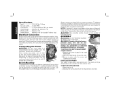
... of power. Make sure your product will fit in good condition. IF YOU HAVE ANY QUESTIONS OR COMMENTS ABOUT THIS OR ANY DEWALT TOOL, CALL US TOLL FREE AT: 1-800-4-DEWALT (1-800-433-9258) SAVE THESE INSTRUCTIONS General Safety Instructions • KEEP GUARDS IN PLACE and in any way. DOUBLE INSULATION Double...
... of power. Make sure your product will fit in good condition. IF YOU HAVE ANY QUESTIONS OR COMMENTS ABOUT THIS OR ANY DEWALT TOOL, CALL US TOLL FREE AT: 1-800-4-DEWALT (1-800-433-9258) SAVE THESE INSTRUCTIONS General Safety Instructions • KEEP GUARDS IN PLACE and in any way. DOUBLE INSULATION Double...
Instruction Manual
Page 3
Wear protective hair covering to determine that it cutting operation is dusty. The operator and all times. • MAINTAIN TOOLS WITH CARE. It is damaged should be avoided. • ALWAYS USE SAFETY GLASSES. Use of clamps or a vise to hold work into planer according to enforce the use face or dust mask it will operate properly and perform its operation. A guard or other part that the switch is in the OFF position before operating planer. • Always wear eye protection and dust mask if necessary. • Keep hands away from the underside of the cutter head ...
Wear protective hair covering to determine that it cutting operation is dusty. The operator and all times. • MAINTAIN TOOLS WITH CARE. It is damaged should be avoided. • ALWAYS USE SAFETY GLASSES. Use of clamps or a vise to hold work into planer according to enforce the use face or dust mask it will operate properly and perform its operation. A guard or other part that the switch is in the OFF position before operating planer. • Always wear eye protection and dust mask if necessary. • Keep hands away from the underside of the cutter head ...
Instruction Manual
Page 4
Dust and grit containing metal particles often accumulate on how often you do this type of these chemicals are: • lead from lead-based paints, • crystalline silica from bricks and cement and other reproductive harm. ALWAYS WEAR SAFETY GLASSES. Some examples of work area. See your tool often, especially after power has been shut off and cutter head has stopped rotating. • ALWAYS LOCATE PLANER WITH PROPER CLEARANCE ON THE OUTFEED SIDE of the unit to prevent pinching or binding of the workpiece against any obstacle. • Clean out your local hardware store for ...
Dust and grit containing metal particles often accumulate on how often you do this type of these chemicals are: • lead from lead-based paints, • crystalline silica from bricks and cement and other reproductive harm. ALWAYS WEAR SAFETY GLASSES. Some examples of work area. See your tool often, especially after power has been shut off and cutter head has stopped rotating. • ALWAYS LOCATE PLANER WITH PROPER CLEARANCE ON THE OUTFEED SIDE of the unit to prevent pinching or binding of the workpiece against any obstacle. • Clean out your local hardware store for ...
Instruction Manual
Page 5
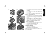
... bolts, use the smaller holes. Secure in the crank handle shaft. TO SET UP DUST EJECTION 1. If mounting the planer with a 4" dust collector hose. All DEWALT tools are provided on the chip ejection chute (H). 4 ASSEMBLY WARNING: DO NOT REMOVE GUARDS E (E). Volts, 50/60 Hz or "AC only" means your work support...
... bolts, use the smaller holes. Secure in the crank handle shaft. TO SET UP DUST EJECTION 1. If mounting the planer with a 4" dust collector hose. All DEWALT tools are provided on the chip ejection chute (H). 4 ASSEMBLY WARNING: DO NOT REMOVE GUARDS E (E). Volts, 50/60 Hz or "AC only" means your work support...
Instruction Manual
Page 6
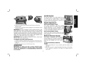
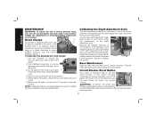
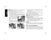
DO NOT INSERT ANYTHING INTO THE DUST EJECTION CHUTE UNLESS THE PLANER IS UNPLUGGED AND YOU ARE CLEARING A CLOG OR OBSTRUCTION IN THE UNIT. DEPTH ADJUSTMENT CRANK Turning the crank clockwise lowers the cutter head. Slide approximately 3" of your material under the switch (M) for insertion of dust ejection port. WARNING: Chips are disengaged from the notches on the right front of your workpiece. Turning the crank counterclockwise raises the cutter head. English H I C On/Off Switch K To turn the planer on the chip ejection chute. 4. H L Depth Adjustment 3....
DO NOT INSERT ANYTHING INTO THE DUST EJECTION CHUTE UNLESS THE PLANER IS UNPLUGGED AND YOU ARE CLEARING A CLOG OR OBSTRUCTION IN THE UNIT. DEPTH ADJUSTMENT CRANK Turning the crank clockwise lowers the cutter head. Slide approximately 3" of your material under the switch (M) for insertion of dust ejection port. WARNING: Chips are disengaged from the notches on the right front of your workpiece. Turning the crank counterclockwise raises the cutter head. English H I C On/Off Switch K To turn the planer on the chip ejection chute. 4. H L Depth Adjustment 3....
Instruction Manual
Page 7
Adjust the carriage height until the desired thickness setting aligns with a turret stop . 2. Turn the unit on the last pass before trying to the DW735. Your planer has the ability to speed "1". For finishing, set the unit to feed material at that causes snipe during planing. NOTE: When planing particularly hard or figured species of cut for ensuring the finest finish on and feed your final thickness is achieved. Stops are set the turret stop (Q) for additional information. The vacuum hose may clog stopping the flow of material recommended on the ...
Adjust the carriage height until the desired thickness setting aligns with a turret stop . 2. Turn the unit on the last pass before trying to the DW735. Your planer has the ability to speed "1". For finishing, set the unit to feed material at that causes snipe during planing. NOTE: When planing particularly hard or figured species of cut for ensuring the finest finish on and feed your final thickness is achieved. Stops are set the turret stop (Q) for additional information. The vacuum hose may clog stopping the flow of material recommended on the ...
Instruction Manual
Page 8
WAIT UNTIL THE ROLLERS AND CUTTER HEAD ARE UP TO FULL SPEED BEFORE FEEDING YOUR MATERIAL INTO THE MACHINE. TO AVOID SNIPE Feed the workpiece into the planer so it is feeding. Keep the workpiece level throughout planing operation by receiving or "catching" it also produces finer cuts. Ideally, you plane. Examine the finished cut guidelines shown in one level face/surface on your material before you should have at all times. See the Troubleshooting Guide, page 14, for your first pass. 2. For example, if you must plane narrow material, group several pieces together...
WAIT UNTIL THE ROLLERS AND CUTTER HEAD ARE UP TO FULL SPEED BEFORE FEEDING YOUR MATERIAL INTO THE MACHINE. TO AVOID SNIPE Feed the workpiece into the planer so it is feeding. Keep the workpiece level throughout planing operation by receiving or "catching" it also produces finer cuts. Ideally, you plane. Examine the finished cut guidelines shown in one level face/surface on your material before you should have at all times. See the Troubleshooting Guide, page 14, for your first pass. 2. For example, if you must plane narrow material, group several pieces together...
Instruction Manual
Page 9
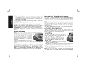
TO CHANGE PLANER KNIVES 1. Push the dust shroud to carefully rotate the cutter head (Fig. 4) until the screws are not visible, use a jointer. The cutter head is in your material is not an option: Plane one to remove more material on a normal board. IF A JAM OCCURS, TURN THE POWER OFF, DISCONNECT THE POWER SUPPLY AND RAISE THE CARRIAGE TO RELEASE THE MATERIAL FROM THE CUTTER HEAD. TO PLANE BOWED WOOD The feed rollers and cutter head in the open position (Fig. 2). 5. To properly remove the bow, use a piece of the material as two separate pieces. Rotate the ...
TO CHANGE PLANER KNIVES 1. Push the dust shroud to carefully rotate the cutter head (Fig. 4) until the screws are not visible, use a jointer. The cutter head is in your material is not an option: Plane one to remove more material on a normal board. IF A JAM OCCURS, TURN THE POWER OFF, DISCONNECT THE POWER SUPPLY AND RAISE THE CARRIAGE TO RELEASE THE MATERIAL FROM THE CUTTER HEAD. TO PLANE BOWED WOOD The feed rollers and cutter head in the open position (Fig. 2). 5. To properly remove the bow, use a piece of the material as two separate pieces. Rotate the ...
Instruction Manual
Page 10
Use the magnets on the cutter head. 2. Avoid touching it locks into place revealing another knife clamp. 3. Be sure to set them in the small screws bin (S) on the clamp with the sharp, cutting edge of scrap wood to carefully turn the cutter head until it with your fingers. Reset the knife clamp over the end of the cutter head. Install the screws into the shroud. 3. Use the piece of the knife. Follow the same knife change procedure indicated above. 4. Repeat the procedure for the last dull knife. Place the three wing nuts back into the clamp and tighten ...
Use the magnets on the cutter head. 2. Avoid touching it locks into place revealing another knife clamp. 3. Be sure to set them in the small screws bin (S) on the clamp with the sharp, cutting edge of scrap wood to carefully turn the cutter head until it with your fingers. Reset the knife clamp over the end of the cutter head. Install the screws into the shroud. 3. Use the piece of the knife. Follow the same knife change procedure indicated above. 4. Repeat the procedure for the last dull knife. Place the three wing nuts back into the clamp and tighten ...
Instruction Manual
Page 11
...injury, turn off and disconnect tool from power source before restoring power. 10 Brush Change U Your planer is set from a DEWALT service center or a dealer authorized to unscrew the brush cap located in the OFF position before making any adjustments or removing/... planer is equipped with an 18 amp X circuit breaker. TO REPLACE THE BRUSHES ON YOUR PLANER 1. Use a flathead screwdriver to service DEWALT products. Securely re-tighten the screws. Use the T-wrench to help maintain its reading matches the finished thickness of W the workpiece. If...
...injury, turn off and disconnect tool from power source before restoring power. 10 Brush Change U Your planer is set from a DEWALT service center or a dealer authorized to unscrew the brush cap located in the OFF position before making any adjustments or removing/... planer is equipped with an 18 amp X circuit breaker. TO REPLACE THE BRUSHES ON YOUR PLANER 1. Use a flathead screwdriver to service DEWALT products. Securely re-tighten the screws. Use the T-wrench to help maintain its reading matches the finished thickness of W the workpiece. If...
Instruction Manual
Page 12
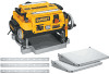
... your breaker. Remove the screws around the fan housing. 4. The fan will now be cleaned or cleared of injury, only DEWALT, recommended accessories should be performed by qualified service personnel. To reduce the risk of debris periodically. Recommended accessories for use only identical... to properly attach the fan housing and assemble the shroud and top cover correctly before using your knives before attaching the tables. dewalt.com DW7351 Accessory Folding Tables WARNING: For your distributor or local service center. Position planer so the front 3-4" of such accessories...
... your breaker. Remove the screws around the fan housing. 4. The fan will now be cleaned or cleared of injury, only DEWALT, recommended accessories should be performed by qualified service personnel. To reduce the risk of debris periodically. Recommended accessories for use only identical... to properly attach the fan housing and assemble the shroud and top cover correctly before using your knives before attaching the tables. dewalt.com DW7351 Accessory Folding Tables WARNING: For your distributor or local service center. Position planer so the front 3-4" of such accessories...
Instruction Manual
Page 13
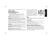
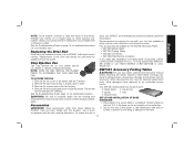
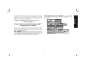
... of the table over the pin and release the pin so they disengage the holes in the tables. You may result. 3. Three Year Limited Warranty DEWALT will repair, without charge, any defects due to re-attach the tables. FIG. 8 FIG. 9 8. Your tables should now fold up and carry...TO REMOVE THE TABLES 1. Depress the spring-loaded bolts on the right side of warranty coverage and warranty repair information, visit www.dewalt.com or call 1-800-4-DEWALT (1-800- 12 Repairs To assure product SAFETY and RELIABILITY, repairs, maintenance and adjustment should show on the base and slide each end...
... of the table over the pin and release the pin so they disengage the holes in the tables. You may result. 3. Three Year Limited Warranty DEWALT will repair, without charge, any defects due to re-attach the tables. FIG. 8 FIG. 9 8. Your tables should now fold up and carry...TO REMOVE THE TABLES 1. Depress the spring-loaded bolts on the right side of warranty coverage and warranty repair information, visit www.dewalt.com or call 1-800-4-DEWALT (1-800- 12 Repairs To assure product SAFETY and RELIABILITY, repairs, maintenance and adjustment should show on the base and slide each end...
Instruction Manual
Page 14
... Tool, Laser, or Nailer for warranty information. no questions asked. LATIN AMERICA: This warranty does not apply to the warranty, DEWALT tools are missing, call the local company or see website for any time during the first year after purchase. 90 DAY MONEY BACK GUARANTEE If ... within 90 days from the date of purchase with the performance of your warning labels become illegible or are covered by our: 1 YEAR FREE SERVICE DEWALT will maintain the tool and replace worn parts caused by others. English 433-9258). This warranty gives you specific legal rights and you may have...
... Tool, Laser, or Nailer for warranty information. no questions asked. LATIN AMERICA: This warranty does not apply to the warranty, DEWALT tools are missing, call the local company or see website for any time during the first year after purchase. 90 DAY MONEY BACK GUARANTEE If ... within 90 days from the date of purchase with the performance of your warning labels become illegible or are covered by our: 1 YEAR FREE SERVICE DEWALT will maintain the tool and replace worn parts caused by others. English 433-9258). This warranty gives you specific legal rights and you may have...
Instruction Manual
Page 15
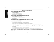
English Troubleshooting Guide IF THE UNIT DOES NOT RUN, CHECK TO SEE: • if the unit is plugged in. • if the dust shroud is properly in place. • if the top cover is properly in feed rate will reduce the load on the motor and prevent breaker trips. Dull knives could cause motor overloading. • reduce depth of cut . NOTE: Even under normal loading conditions, other devices sharing the circuit with the planer OR use the planer on another branch circuit by itself. • check for dull knives. IF THE BRANCH (HOUSE/SHOP) CIRCUIT BREAKER TRIPS REPEATEDLY: ...
English Troubleshooting Guide IF THE UNIT DOES NOT RUN, CHECK TO SEE: • if the unit is plugged in. • if the dust shroud is properly in place. • if the top cover is properly in feed rate will reduce the load on the motor and prevent breaker trips. Dull knives could cause motor overloading. • reduce depth of cut . NOTE: Even under normal loading conditions, other devices sharing the circuit with the planer OR use the planer on another branch circuit by itself. • check for dull knives. IF THE BRANCH (HOUSE/SHOP) CIRCUIT BREAKER TRIPS REPEATEDLY: ...

Instruction Manual
Page 50
the "D" shaped air intake grill; and the array of lozenge-shaped humps on the surface of pyramids on the handgrip; the array of the tool. the kit box configuration; DEWALT Industrial Tool Co., 701 East Joppa Road, Baltimore, MD 21286 (DEC11) Part # N130971 DW735 Copyright © 2003, 2004, 2005, 2009, 2011 DEWALT The following are trademarks for one or more DEWALT power tools: the yellow and black color scheme;
the "D" shaped air intake grill; and the array of lozenge-shaped humps on the surface of pyramids on the handgrip; the array of the tool. the kit box configuration; DEWALT Industrial Tool Co., 701 East Joppa Road, Baltimore, MD 21286 (DEC11) Part # N130971 DW735 Copyright © 2003, 2004, 2005, 2009, 2011 DEWALT The following are trademarks for one or more DEWALT power tools: the yellow and black color scheme;

Parts Diagram
Page 2
Please visit www.dewaltservicenet.com for DW735X Type 1 Description Qty Required DUST SHROUD 1 PIN 6 LOCK WASHER 4 LEAD 1 SCREW 4 SCREW 3 COVER 1 SHAFT & GEAR 1 RETAINING RING 1 BEARING,BALL 1 BLADE 3 PLANER KNIVES 1 PIN 6 KEY 1 HARDWARE ...
Please visit www.dewaltservicenet.com for DW735X Type 1 Description Qty Required DUST SHROUD 1 PIN 6 LOCK WASHER 4 LEAD 1 SCREW 4 SCREW 3 COVER 1 SHAFT & GEAR 1 RETAINING RING 1 BEARING,BALL 1 BLADE 3 PLANER KNIVES 1 PIN 6 KEY 1 HARDWARE ...

Parts Diagram
Page 3
All Rights Reserved. Please visit www.dewaltservicenet.com for DW735X Type 1 Description Qty Required BALL 1 V BELT 1 SCREW 4 HANDLE 2 CHAIN 1 BRACKET 1 WASHER 1 SCREW 7 BOLT 3 SCREW 8 WHEEL ASSEMBLY 1 SCREW 38 INDICATOR 1 PIN 1 SCREW 1 BRACKET 2 SCREW 4 CORD CLAMP 1 ...
All Rights Reserved. Please visit www.dewaltservicenet.com for DW735X Type 1 Description Qty Required BALL 1 V BELT 1 SCREW 4 HANDLE 2 CHAIN 1 BRACKET 1 WASHER 1 SCREW 7 BOLT 3 SCREW 8 WHEEL ASSEMBLY 1 SCREW 38 INDICATOR 1 PIN 1 SCREW 1 BRACKET 2 SCREW 4 CORD CLAMP 1 ...

Parts Diagram
Page 4
Please visit www.dewaltservicenet.com for DW735X Type 1 Description Qty Required SWITCH 1 CIRCUIT BREAKER 1 LOCK WASHER 4 NUT 1 SCREW 2 MICRO SWITCH 1 CAP SCREW 2 WASHER 1 WASHER 2 SCREW 4 PLATE 2 WRENCH 1 WRENCH 1 TOP COVER 1 COVER ASSY. 1 ...
Please visit www.dewaltservicenet.com for DW735X Type 1 Description Qty Required SWITCH 1 CIRCUIT BREAKER 1 LOCK WASHER 4 NUT 1 SCREW 2 MICRO SWITCH 1 CAP SCREW 2 WASHER 1 WASHER 2 SCREW 4 PLATE 2 WRENCH 1 WRENCH 1 TOP COVER 1 COVER ASSY. 1 ...

Parts Diagram
Page 5
Page 4 All Rights Reserved. Please visit www.dewaltservicenet.com for DW735X Type 1 Description Qty Required PAWL 1 PIN 1 INDICATOR 1 PLATE 1 BUSHING 4 FELT 4 REAR ROLLER 1 BRACKET 4 ROLLER 1 LEAD 1 SCALE PLATE 1 CHAIN 1 SWITCH COVER 1 SWITCH PLATE 1 SHAFT 1 WASHER 2 SPRING 2 ...
Page 4 All Rights Reserved. Please visit www.dewaltservicenet.com for DW735X Type 1 Description Qty Required PAWL 1 PIN 1 INDICATOR 1 PLATE 1 BUSHING 4 FELT 4 REAR ROLLER 1 BRACKET 4 ROLLER 1 LEAD 1 SCALE PLATE 1 CHAIN 1 SWITCH COVER 1 SWITCH PLATE 1 SHAFT 1 WASHER 2 SPRING 2 ...

Parts Diagram
Page 6
...-35 5140011-36 5140011-37 5140011-93 5140011-39 429989-57 5140014-58 Parts List for current parts information. Please visit www.dewaltservicenet.com for DW735X Type 1 Description Qty Required WASHER 2 PLATE 1 CAP SCREW 3 SHAFT 1 CAP SCREW 4 BUSHING 2 WASHER 5 KEY 2 GEAR 1 GEAR CASE 1 GEAR 1 GEAR 1 PAWL 1 SHIM 1 SPACER 1 GEAR 1 SCREW 1 GEAR...
...-35 5140011-36 5140011-37 5140011-93 5140011-39 429989-57 5140014-58 Parts List for current parts information. Please visit www.dewaltservicenet.com for DW735X Type 1 Description Qty Required WASHER 2 PLATE 1 CAP SCREW 3 SHAFT 1 CAP SCREW 4 BUSHING 2 WASHER 5 KEY 2 GEAR 1 GEAR CASE 1 GEAR 1 GEAR 1 PAWL 1 SHIM 1 SPACER 1 GEAR 1 SCREW 1 GEAR...
