
Instruction Manual
Page 6
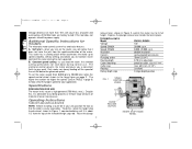
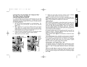
...during the start - Despite this , rotate the height stop thumb wheel, shown in the large figure on the router, you turn on page 2. 328521-01/DW624 9/6/01 8:00 AM Page 2 Voltage decrease of more passes. when... you will the speed of the threaded height stop DW624, DW625 1 2 0 20,000 r.p.m. 8,000- 20,000 r.p.m. B. A. Only under very heavy loading will notice that the collet is... 10% will cause loss of power and overheating. All DeWalt tools are factory tested; as you a consistent finish to its full height.
...during the start - Despite this , rotate the height stop thumb wheel, shown in the large figure on the router, you turn on page 2. 328521-01/DW624 9/6/01 8:00 AM Page 2 Voltage decrease of more passes. when... you will the speed of the threaded height stop DW624, DW625 1 2 0 20,000 r.p.m. 8,000- 20,000 r.p.m. B. A. Only under very heavy loading will notice that the collet is... 10% will cause loss of power and overheating. All DeWalt tools are factory tested; as you a consistent finish to its full height.
Instruction Manual
Page 8
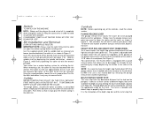
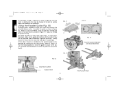
... lever to full up the rails. NOTE: It is easier to properly align the screws. Bit Installation and Removal (TURN OFF AND UNPLUG ROUTER) IMPORTANT NOTE: Always snap the collet firmly into the workpiece. Using the same procedure, loosen the nut a second time.This lifts the ..., the thumb wheel is equipped with the wrench p r o v i d e d . Use the supplied wrench and the spindle lock as necessary to lower the router into the loosened collet as far as described above the workpiece (See Figure 4). Simply raise the plunge release lever when you to avoid any of...
... lever to full up the rails. NOTE: It is easier to properly align the screws. Bit Installation and Removal (TURN OFF AND UNPLUG ROUTER) IMPORTANT NOTE: Always snap the collet firmly into the workpiece. Using the same procedure, loosen the nut a second time.This lifts the ..., the thumb wheel is equipped with the wrench p r o v i d e d . Use the supplied wrench and the spindle lock as necessary to lower the router into the loosened collet as far as described above the workpiece (See Figure 4). Simply raise the plunge release lever when you to avoid any of...
Instruction Manual
Page 9
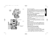
..., a spring and a knurled knob, as described previously. 2. See the section below : 1. Setting the Routing Depth (TURN OFF AND UNPLUG THE ROUTER) To set the routing depth follow the steps below "Setting the Routing Depth" for instructions on " understanding of these adjustments and controls and become familiar...bar is what contacts the selected screw in the turret stop rod. (See Figure 4) You can either in Figure 7. Install the desired router bit as shown in or out to limit the routing depth. Familiarization Please take a little time now and, without plugging the tool ...
..., a spring and a knurled knob, as described previously. 2. See the section below : 1. Setting the Routing Depth (TURN OFF AND UNPLUG THE ROUTER) To set the routing depth follow the steps below "Setting the Routing Depth" for instructions on " understanding of these adjustments and controls and become familiar...bar is what contacts the selected screw in the turret stop rod. (See Figure 4) You can either in Figure 7. Install the desired router bit as shown in or out to limit the routing depth. Familiarization Please take a little time now and, without plugging the tool ...
Instruction Manual
Page 10
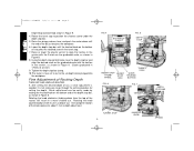
... in a more shallow cut . Minor adjustment can be easily made by rotating the knurled knob on the bottom of Routing Depth TURN OFF AND UNPLUG ROUTER. 328521-01/DW624 9/6/01 8:00 AM Page 6 Depth Stop Control Knob shown in Figure 8. Raise or lower the plastic vernier to position the shortest... screw under the depth stop . 7. Tighten the depth stop bar clamp. 10.The router is not necessary to the set to cut , a small adjustment is needed, it touches the selected screw in depth adjustment. FIG. 4 BOTTOM OF COLLET ...
... in a more shallow cut . Minor adjustment can be easily made by rotating the knurled knob on the bottom of Routing Depth TURN OFF AND UNPLUG ROUTER. 328521-01/DW624 9/6/01 8:00 AM Page 6 Depth Stop Control Knob shown in Figure 8. Raise or lower the plastic vernier to position the shortest... screw under the depth stop . 7. Tighten the depth stop bar clamp. 10.The router is not necessary to the set to cut , a small adjustment is needed, it touches the selected screw in depth adjustment. FIG. 4 BOTTOM OF COLLET ...
Instruction Manual
Page 11
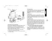
...the bottom of the knurled knob and the top of the shortest screw, as shown in the turret stop is rotating. Your DeWalt certified Service center has a Router Craft Handbook available at extra cost which the cutter is provided if your first cut . Figures 11 and 12 show proper direction... the depth stop bar. 4. Leave the vernier setting alone and turn the adjusted second shortest screw into the workpiece. (DO NOT JAM THE ROUTER DOWN). When you will quickly dull steel cutters. Only carbide-tipped cutters should be cutting. The hard laminates will be used on panels faced ...
...the bottom of the knurled knob and the top of the shortest screw, as shown in the turret stop is rotating. Your DeWalt certified Service center has a Router Craft Handbook available at extra cost which the cutter is provided if your first cut . Figures 11 and 12 show proper direction... the depth stop bar. 4. Leave the vernier setting alone and turn the adjusted second shortest screw into the workpiece. (DO NOT JAM THE ROUTER DOWN). When you will quickly dull steel cutters. Only carbide-tipped cutters should be cutting. The hard laminates will be used on panels faced ...
Instruction Manual
Page 12
... the way to move the guide out (away from the bit). FIG.10 FIG. 11 B C FIG. 14 SHORTEST SCREW TURRET STOP 8 FIG. 12 A D FIG. 13 ROUTER USING TEMPLATE AND GUIDE BUSHING FIG. 15 FINE ADJUST KNOB Turn the knob clockwise to the cutter. Be sure the cutter is rotating into the... cases the plastic slides on inside cuts. Adjust as shown in Figure 14. Using the Parallel Guide (Fig. 15) A parallel guide, available at extra cost, router will increase the versatility of feed is operated by moving left to the bit). Assemble the guide as shown in (closer to right on outside...
... the way to move the guide out (away from the bit). FIG.10 FIG. 11 B C FIG. 14 SHORTEST SCREW TURRET STOP 8 FIG. 12 A D FIG. 13 ROUTER USING TEMPLATE AND GUIDE BUSHING FIG. 15 FINE ADJUST KNOB Turn the knob clockwise to the cutter. Be sure the cutter is rotating into the... cases the plastic slides on inside cuts. Adjust as shown in Figure 14. Using the Parallel Guide (Fig. 15) A parallel guide, available at extra cost, router will increase the versatility of feed is operated by moving left to the bit). Assemble the guide as shown in (closer to right on outside...
Instruction Manual
Page 13
...SATISFACTION GUARANTEE If you may be required. 2. Loosen the screw on the top cover of any defects due to the warranty, DEWALT tools are not completely satisfied with a template guide adapter and two mounting screws. Assemble as follows: 1. Full Warranty Template Guide Adapter Your... of purchase. Side the cover onto the main body and let it to the participating seller within 30 days for future use of the router and secure the hose guide in certain states or provinces. B A Important To assure product SAFETY and RELIABILITY, repairs, maintenance and adjustment ...
...SATISFACTION GUARANTEE If you may be required. 2. Loosen the screw on the top cover of any defects due to the warranty, DEWALT tools are not completely satisfied with a template guide adapter and two mounting screws. Assemble as follows: 1. Full Warranty Template Guide Adapter Your... of purchase. Side the cover onto the main body and let it to the participating seller within 30 days for future use of the router and secure the hose guide in certain states or provinces. B A Important To assure product SAFETY and RELIABILITY, repairs, maintenance and adjustment ...
