

Instruction Manual
Page 2
328521-01/DW624 9/6/01 8:00 AM Page 2 DEWALT Industrial Tool Co., 701 East Joppa Road, Baltimore, MD 21286 DW624. DW625 (DEC99) Printed in Switzerland Copyright © 1999 Form No. 328521-01
328521-01/DW624 9/6/01 8:00 AM Page 2 DEWALT Industrial Tool Co., 701 East Joppa Road, Baltimore, MD 21286 DW624. DW625 (DEC99) Printed in Switzerland Copyright © 1999 Form No. 328521-01
Instruction Manual
Page 4
... of a heavy-duty tool. They can be toxic. Also use circular saw for cutting tree limbs or logs. • DRESS PROPERLY. Keep cord from tool before servicing, and when changing accessories. • REMOVE ADJUSTING KEYS AND WRENCHES. Use clamps or a vise to see that keys and adjusting wrenches are removed from heat, oil, and sharp edges. • SECURE WORK. Keep tools sharp and clean for lubricating and changing accessories. Inspect extension cords periodically and replace if damaged. Form...
... of a heavy-duty tool. They can be toxic. Also use circular saw for cutting tree limbs or logs. • DRESS PROPERLY. Keep cord from tool before servicing, and when changing accessories. • REMOVE ADJUSTING KEYS AND WRENCHES. Use clamps or a vise to see that keys and adjusting wrenches are removed from heat, oil, and sharp edges. • SECURE WORK. Keep tools sharp and clean for lubricating and changing accessories. Inspect extension cords periodically and replace if damaged. Form...
Instruction Manual
Page 5
.... A guard or other conditions that may be operated only with alternating current and never with the nameplate marking. Watch what you and the tool's electrical system. Recommended Minimum Wire Size for Extension Cords Total Length of normal safety precautions when operating this instruction manual. Check for added protection against injury resulting from a possible electrical insulation failure within the tool. SAVE THESE INSTRUCTIONS FOR FUTURE USE. REPLACEMENT PARTS.
.... A guard or other conditions that may be operated only with alternating current and never with the nameplate marking. Watch what you and the tool's electrical system. Recommended Minimum Wire Size for Extension Cords Total Length of normal safety precautions when operating this instruction manual. Check for added protection against injury resulting from a possible electrical insulation failure within the tool. SAVE THESE INSTRUCTIONS FOR FUTURE USE. REPLACEMENT PARTS.
Instruction Manual
Page 6
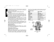
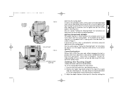
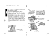
... of material in this tool does not operate, check the power supply. Raise the plunge 2 release lever, shown in place. double insulated spring loaded twin column 70mm (2-3/4") 0-70 mm adjustable precision collet, size 1/2"-1/4" max. 63.5 mm (2-1/2") (shallow) 3 stage depth position FIG. 1 SPEED CONTROL WHEEL 1/2 QUICK RELEASE BUTTON HEIGHT STOP THUMB WHEEL The higher the number the higher the speed. Operating Instructions TURN OFF AND UNPLUG ROUTER NOTE: Before installing a router bit in your unit, position...
... of material in this tool does not operate, check the power supply. Raise the plunge 2 release lever, shown in place. double insulated spring loaded twin column 70mm (2-3/4") 0-70 mm adjustable precision collet, size 1/2"-1/4" max. 63.5 mm (2-1/2") (shallow) 3 stage depth position FIG. 1 SPEED CONTROL WHEEL 1/2 QUICK RELEASE BUTTON HEIGHT STOP THUMB WHEEL The higher the number the higher the speed. Operating Instructions TURN OFF AND UNPLUG ROUTER NOTE: Before installing a router bit in your unit, position...
Instruction Manual
Page 7
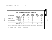
... 9/6/01 8:00 AM Page 3 SPEED SELECTION CHART TABLE 1: RECOMMENDATION FOR THE CORRECT CHOICE OF SPEED Material Model #DW624/DW625 Hardwood, e.g., oak Softwood, e.g., pine Plastic-laminated chipboard Plastics Cutter Diam. Small (1/2") Medium (1/2"-1 1/8") Large (over-1 1/8") Small (1/2") Medium (1/2"-1 1/8") Large (over-1 1/8") Small (1/2") Medium (1/2"-1 1/8") Large (over-1 1/8") Small (1/2") Medium (1/2"-1 1/8") Large (over-1 1/8") Stage 1 8,000 rpm - - X Electronic Control Settings Stage 2 12,000 rpm Stage...
... 9/6/01 8:00 AM Page 3 SPEED SELECTION CHART TABLE 1: RECOMMENDATION FOR THE CORRECT CHOICE OF SPEED Material Model #DW624/DW625 Hardwood, e.g., oak Softwood, e.g., pine Plastic-laminated chipboard Plastics Cutter Diam. Small (1/2") Medium (1/2"-1 1/8") Large (over-1 1/8") Small (1/2") Medium (1/2"-1 1/8") Large (over-1 1/8") Small (1/2") Medium (1/2"-1 1/8") Large (over-1 1/8") Small (1/2") Medium (1/2"-1 1/8") Large (over-1 1/8") Stage 1 8,000 rpm - - X Electronic Control Settings Stage 2 12,000 rpm Stage...
Instruction Manual
Page 8
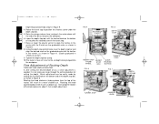
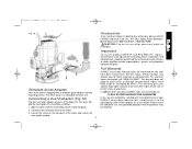
... the cord set by limiting the travel , depress the lever. Push firmly so that serve to define the depth of cut by selecting the screw of the collet nut and insert the new collet. It consists of three screws of different lengths that it very easy to avoid any of a turn and then become tight again. Bit Installation and Removal (TURN OFF AND UNPLUG ROUTER...
... the cord set by limiting the travel , depress the lever. Push firmly so that serve to define the depth of cut by selecting the screw of the collet nut and insert the new collet. It consists of three screws of different lengths that it very easy to avoid any of a turn and then become tight again. Bit Installation and Removal (TURN OFF AND UNPLUG ROUTER...
Instruction Manual
Page 9
... each can either in Figure 7. Install the desired router bit as shown in or out to get the most out of the depth stop bar to tighten the hex nut at the bottom and then turning the screw either turn the thumb wheel or use the handy quick release button discussed above. 5 3. Adjust the depth stop bar is a threaded shaft, a spring and a knurled knob, as described previously. 2. At the...
... each can either in Figure 7. Install the desired router bit as shown in or out to get the most out of the depth stop bar to tighten the hex nut at the bottom and then turning the screw either turn the thumb wheel or use the handy quick release button discussed above. 5 3. Adjust the depth stop bar is a threaded shaft, a spring and a knurled knob, as described previously. 2. At the...
Instruction Manual
Page 10
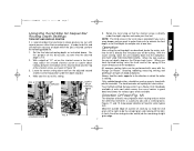
... cut . FIG. 4 BOTTOM OF COLLET FIG. 5 DEPTH STOP HEIGHT STOP HEIGHT THUMB STOP WHEEL ROD QUICK RELEASE BUTTON TURRET STOP FIG. 6 FIG. 7 VERNIER TURRET STOP 6 KNURLED KNOB DEPTH STOP BAR SPRING Tighten the depth stop . 7. Rotate the turret stop bar. 5. Fine Adjustment of the knob represents about 1 mm in Figure 8. 8. Rotating the knob clockwise (looking down until the knurled knob on the graduated scale, as shown in depth adjustment. One complete rotation of Routing Depth TURN...
... cut . FIG. 4 BOTTOM OF COLLET FIG. 5 DEPTH STOP HEIGHT STOP HEIGHT THUMB STOP WHEEL ROD QUICK RELEASE BUTTON TURRET STOP FIG. 6 FIG. 7 VERNIER TURRET STOP 6 KNURLED KNOB DEPTH STOP BAR SPRING Tighten the depth stop . 7. Rotate the turret stop bar. 5. Fine Adjustment of the knob represents about 1 mm in Figure 8. 8. Rotating the knob clockwise (looking down until the knurled knob on the graduated scale, as shown in depth adjustment. One complete rotation of Routing Depth TURN...
Instruction Manual
Page 11
... be cutting. Mold the outside edge of a piece of the workpiece. Set the final desired routing depth as shown in great detail and shows the various types of 1/2" set depth, depress the Plunge Lock Lever. Make your final cut. Rotate the turret stop bar. 4. Your DeWalt certified Service center has a Router Craft Handbook available at this setting. Operation After setting the cutting depth as described, locate the router such that the bit is...
... be cutting. Mold the outside edge of a piece of the workpiece. Set the final desired routing depth as shown in great detail and shows the various types of 1/2" set depth, depress the Plunge Lock Lever. Make your final cut. Rotate the turret stop bar. 4. Your DeWalt certified Service center has a Router Craft Handbook available at this setting. Operation After setting the cutting depth as described, locate the router such that the bit is...
Instruction Manual
Page 12
... 19. In some cases the plastic slides on each slide and adjust it 's fully assembled, insert the two bars through the holes in the router base as needed for parallel routing. FIG.10 FIG. 11 B C FIG. 14 SHORTEST SCREW TURRET STOP 8 FIG. 12 A D FIG. 13 ROUTER USING TEMPLATE AND GUIDE BUSHING FIG. 15 FINE ADJUST KNOB Simply loosen the two screws on the guide will interfere with the...
... 19. In some cases the plastic slides on each slide and adjust it 's fully assembled, insert the two bars through the holes in the router base as needed for parallel routing. FIG.10 FIG. 11 B C FIG. 14 SHORTEST SCREW TURRET STOP 8 FIG. 12 A D FIG. 13 ROUTER USING TEMPLATE AND GUIDE BUSHING FIG. 15 FINE ADJUST KNOB Simply loosen the two screws on the guide will interfere with the...
Instruction Manual
Page 13
.... B A Important To assure product SAFETY and RELIABILITY, repairs, maintenance and adjustment (including brush inspection and replacement) should be performed by authorized service centers or other accessory might be required. 2. Full Warranty Template Guide Adapter Your router comes equipped with the performance of any other qualified service organizations, always using identical replacement parts. For warranty repair information, call 1-800-4-DEWALT (1-800-433-9258). This warranty gives you specific legal rights and you...
.... B A Important To assure product SAFETY and RELIABILITY, repairs, maintenance and adjustment (including brush inspection and replacement) should be performed by authorized service centers or other accessory might be required. 2. Full Warranty Template Guide Adapter Your router comes equipped with the performance of any other qualified service organizations, always using identical replacement parts. For warranty repair information, call 1-800-4-DEWALT (1-800-433-9258). This warranty gives you specific legal rights and you...


