
Instruction Manual
Page 1
... the tool electrically malfunctions, breaks down on the base. To change collet sizes, unscrew the collet assembly as needed for appropriate conditions. The collet and the collet nut are trademarks for which it from the user. See the heading Bit Installation and Removal. 2. Open the locking lever (D) and turn it could create a risk of this manual. Turn the depth adjustment ring along with the second wrench. [On the DW618, depress the spindle lock button (I ) on...
... the tool electrically malfunctions, breaks down on the base. To change collet sizes, unscrew the collet assembly as needed for appropriate conditions. The collet and the collet nut are trademarks for which it from the user. See the heading Bit Installation and Removal. 2. Open the locking lever (D) and turn it could create a risk of this manual. Turn the depth adjustment ring along with the second wrench. [On the DW618, depress the spindle lock button (I ) on...

Instruction Manual
Page 2
... cone, tighten the subbase screws. Trigger Lock To lock the trigger, pull the trigger switch (N) completely, then push the trigger lock button (O). Using the wrench(es) provided, turn approximately 3/4 of the depth adjustment rod can damage the collet. To remove a bit, hold the spindle shaft.] 2. Install the desired collet by turning the wingscrew (DD) counterclockwise. 4. See the heading Bit Installation and Removal. 2. Using a Parallel Fence A parallel fence (DW6913) is provided. SET-UP: PLUNGE BASE (Fig. 8) Motor Quick Release CAUTION: Turn the router off and...
... cone, tighten the subbase screws. Trigger Lock To lock the trigger, pull the trigger switch (N) completely, then push the trigger lock button (O). Using the wrench(es) provided, turn approximately 3/4 of the depth adjustment rod can damage the collet. To remove a bit, hold the spindle shaft.] 2. Install the desired collet by turning the wingscrew (DD) counterclockwise. 4. See the heading Bit Installation and Removal. 2. Using a Parallel Fence A parallel fence (DW6913) is provided. SET-UP: PLUNGE BASE (Fig. 8) Motor Quick Release CAUTION: Turn the router off and...
Parts Diagram
Page 2
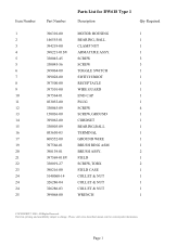
... www.dewaltservicenet.com for DW618 Type 1 Description Qty Required 396310-00 MOTOR HOUSING 1 146555-01 BEARING, BALL 1 394219-00 CLAMP NUT 1 398221-01SV ARMATURE ASSY. 1 330045-45 SCREW 3 330045-56 SCREW 3 399064-00 TOGGLE SWITCH 1 399028-00 SWITCH BOOT 1 397500-00 RECEPTACLE 1 397501-00 WIRE GUARD 1 397564-01 END CAP 1 033055-00 PLUG 1 330045-09 SCREW 4 150036-00 SCREW,GROUND 1 399063-00 CORDSET...
... www.dewaltservicenet.com for DW618 Type 1 Description Qty Required 396310-00 MOTOR HOUSING 1 146555-01 BEARING, BALL 1 394219-00 CLAMP NUT 1 398221-01SV ARMATURE ASSY. 1 330045-45 SCREW 3 330045-56 SCREW 3 399064-00 TOGGLE SWITCH 1 399028-00 SWITCH BOOT 1 397500-00 RECEPTACLE 1 397501-00 WIRE GUARD 1 397564-01 END CAP 1 033055-00 PLUG 1 330045-09 SCREW 4 150036-00 SCREW,GROUND 1 399063-00 CORDSET...
Parts Diagram
Page 3
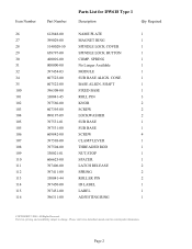
Parts list, pricing, and availability subject to change. CONE 1 BASE ALIGN. Please visit www.dewaltservicenet.com for DW618 Type 1 Description Qty Required NAME PLATE 1 MAGNET RING 1 SPINDLE LOCK COVER 1 SPINDLE LOCK BUTTON 1 COMP. SHAFT 1 FIXED BASE 1 ROLL PIN 3 KNOB 2 SCREW 2 LOCKWASHER 2 SUB BASE 1 SUB BASE 1 SCREW 4 CLAMP LEVER 1 THREADED ROD 1 NUT,STOP 1 SPACER 1 LATCH RELEASE 2 SPRING 2 ROLLER PIN 2 ID LABEL 1 LABEL 1 ADJUSTING RING 1 COPYRIGHT© 2005. Page 2 Item Number 26 27 28 29 30 31 32 34 35 100 101...
Parts list, pricing, and availability subject to change. CONE 1 BASE ALIGN. Please visit www.dewaltservicenet.com for DW618 Type 1 Description Qty Required NAME PLATE 1 MAGNET RING 1 SPINDLE LOCK COVER 1 SPINDLE LOCK BUTTON 1 COMP. SHAFT 1 FIXED BASE 1 ROLL PIN 3 KNOB 2 SCREW 2 LOCKWASHER 2 SUB BASE 1 SUB BASE 1 SCREW 4 CLAMP LEVER 1 THREADED ROD 1 NUT,STOP 1 SPACER 1 LATCH RELEASE 2 SPRING 2 ROLLER PIN 2 ID LABEL 1 LABEL 1 ADJUSTING RING 1 COPYRIGHT© 2005. Page 2 Item Number 26 27 28 29 30 31 32 34 35 100 101...

Parts Diagram
Page 4
Page 3 Parts list, pricing, and availability subject to change. All Rights Reserved. Please visit www.dewaltservicenet.com for DW618 Type 1 Description Qty Required ADJUSTING RING 1 KIT BOX 1 COPYRIGHT© 2005. Item Number 117 861 Part Number 612054-00 397683-00 Parts List for current parts information.
Page 3 Parts list, pricing, and availability subject to change. All Rights Reserved. Please visit www.dewaltservicenet.com for DW618 Type 1 Description Qty Required ADJUSTING RING 1 KIT BOX 1 COPYRIGHT© 2005. Item Number 117 861 Part Number 612054-00 397683-00 Parts List for current parts information.


