
Instruction Manual
Page 1
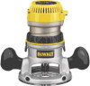
... by poorly maintained tools. Be sure your body is in tools that the router bit is achieved. "120 V~" means your work . If the toggle switch is grounded. Inserting the Motor into the base by depressing the spindle lock button (I ) to carry electricity away from the power source before making any adjustments, changing accessories, or storing the tool. Insert the motor into the Fixed Base (Fig. 3) CAUTION: Turn the router off . NOTE: Guide pin grooves are specially...
... by poorly maintained tools. Be sure your body is in tools that the router bit is achieved. "120 V~" means your work . If the toggle switch is grounded. Inserting the Motor into the base by depressing the spindle lock button (I ) to carry electricity away from the power source before making any adjustments, changing accessories, or storing the tool. Insert the motor into the Fixed Base (Fig. 3) CAUTION: Turn the router off . NOTE: Guide pin grooves are specially...

Instruction Manual
Page 2
... router bit into the hose adapter. 4. This will center the subbase. 5. OPERATION: D-HANDLE BASE Knob Locations Grip the D-Handle with the fence. Trigger Lock To lock the trigger, pull the trigger switch (N) completely, then push the trigger lock button (O). The router will go and then pull it from your DEWALT Power Tool, Laser, or Nailer for any defects due to the desired depth. To install a bit, insert the round shank of a turn approximately 3/4 of the desired router bit into the base and clamp the locking lever...
... router bit into the hose adapter. 4. This will center the subbase. 5. OPERATION: D-HANDLE BASE Knob Locations Grip the D-Handle with the fence. Trigger Lock To lock the trigger, pull the trigger switch (N) completely, then push the trigger lock button (O). The router will go and then pull it from your DEWALT Power Tool, Laser, or Nailer for any defects due to the desired depth. To install a bit, insert the round shank of a turn approximately 3/4 of the desired router bit into the base and clamp the locking lever...
Parts Diagram
Page 3
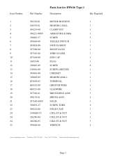
... 17 18 19 20 21 22 23 24 24 24 25 Part Number Parts List for DW616 Type 1 Description Qty Required 396310-01 MOTOR HOUSING 1 146555-01 BEARING, BALL 1 394219-00 CLAMP NUT 1 398221-00SV ARMATURE & BRG. 1 330045-57 SCREW 3 399064-00 TOGGLE SWITCH 1 399028-00 SWITCH BOOT 1 397500-00 RECEPTACLE 1 397501-00 WIRE GUARD 1 397564-00 END CAP 1 33055-00 PLUG 1 330045-09...
... 17 18 19 20 21 22 23 24 24 24 25 Part Number Parts List for DW616 Type 1 Description Qty Required 396310-01 MOTOR HOUSING 1 146555-01 BEARING, BALL 1 394219-00 CLAMP NUT 1 398221-00SV ARMATURE & BRG. 1 330045-57 SCREW 3 399064-00 TOGGLE SWITCH 1 399028-00 SWITCH BOOT 1 397500-00 RECEPTACLE 1 397501-00 WIRE GUARD 1 397564-00 END CAP 1 33055-00 PLUG 1 330045-09...
Parts Diagram
Page 4
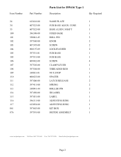
SHAFT 1 FIXED BASE 1 ROLL PIN 3 KNOB 2 SCREW 2 LOCKWASHER 2 SUB BASE 1 SUB BASE 1 SCREW 4 CLAMP LEVER 1 THREADED ROD 1 NUT,STOP 1 SPACER 1 LATCH RELEASE 2 SPRING 2 ROLLER PIN 2 ID LABEL 1 LABEL 1 ADJUSTING RING 1 ADJUSTING RING 1 KIT BOX 1 MOTOR ASSEMBLY 1 www.toolpartspro.com Toll Free: 800 735 8665 Fax: 760 747 2626 Email:[email protected] Page 2 Item Number 26 34 35 100 101...397450-00 397451-00 396311-00 612054-00 397683-00 397591-00 Parts List for DW616 Type 1 Description Qty Required NAME PLATE 1 SUB BASE ALIGN. CONE 1 BASE ALIGN.
SHAFT 1 FIXED BASE 1 ROLL PIN 3 KNOB 2 SCREW 2 LOCKWASHER 2 SUB BASE 1 SUB BASE 1 SCREW 4 CLAMP LEVER 1 THREADED ROD 1 NUT,STOP 1 SPACER 1 LATCH RELEASE 2 SPRING 2 ROLLER PIN 2 ID LABEL 1 LABEL 1 ADJUSTING RING 1 ADJUSTING RING 1 KIT BOX 1 MOTOR ASSEMBLY 1 www.toolpartspro.com Toll Free: 800 735 8665 Fax: 760 747 2626 Email:[email protected] Page 2 Item Number 26 34 35 100 101...397450-00 397451-00 396311-00 612054-00 397683-00 397591-00 Parts List for DW616 Type 1 Description Qty Required NAME PLATE 1 SUB BASE ALIGN. CONE 1 BASE ALIGN.

