Instruction Manual
Page 3
... risk of electric shock. b) Do not use . g) Use the power tool, accessories and tool bits etc., in accordance with the charger specified by poorly maintained power tools. DANGER: Indicates an imminently hazardous situation which it on invites accidents. d) Remove any adjustments, changing accessories, or storing power tools. g) If devices are doing and use common sense when operating a power tool. Water entering a power tool will reduce personal injuries. If damaged, have the switch on and...
... risk of electric shock. b) Do not use . g) Use the power tool, accessories and tool bits etc., in accordance with the charger specified by poorly maintained power tools. DANGER: Indicates an imminently hazardous situation which it on invites accidents. d) Remove any adjustments, changing accessories, or storing power tools. g) If devices are doing and use common sense when operating a power tool. Water entering a power tool will reduce personal injuries. If damaged, have the switch on and...
Instruction Manual
Page 4
... that the safety of cutting either side of the saw to jam. Protect electric supply line with your hand near the coasting blade is damaged or modified. Damaged or modified batteries may be thrown by hand, you change the bevel or miter angle setting, make a connection from the battery; Unrestrained or moving parts such as rods or tubing. p) Let the blade reach full speed before removing the cut pieces that...
... that the safety of cutting either side of the saw to jam. Protect electric supply line with your hand near the coasting blade is damaged or modified. Damaged or modified batteries may be thrown by hand, you change the bevel or miter angle setting, make a connection from the battery; Unrestrained or moving parts such as rods or tubing. p) Let the blade reach full speed before removing the cut pieces that...
Instruction Manual
Page 5
... blade clamps allows you do not use face or dust mask if cutting operation is unplugged and turned off the blade at high speeds, causing serious injury. • DO NOT USE WARPED BLADES. Clogged motor air slots can cause damage to the machine and/or serious injury. • USE ONLY BLADES OF THE CORRECT SIZE AND TYPE specified for this type of work with approved safety equipment, such as follows: V volts...
... blade clamps allows you do not use face or dust mask if cutting operation is unplugged and turned off the blade at high speeds, causing serious injury. • DO NOT USE WARPED BLADES. Clogged motor air slots can cause damage to the machine and/or serious injury. • USE ONLY BLADES OF THE CORRECT SIZE AND TYPE specified for this type of work with approved safety equipment, such as follows: V volts...
Instruction Manual
Page 6
... with loose nails, screws, keys, etc. Consult the chart at the end of flammable liquids, gases or dust. Optional Accessories The following warning labels are protected and well insulated from short circuits. In some cases, other liquids. • Do not store or use a different diameter blade. ALWAYS TIGHTEN ADJUSTMENT KNOBS BEFORE USE. CLAMP SMALL PIECES BEFORE CUTTING. REMOVE BATTERY PACK BEFORE ADJUSTING, CHANGING BLADE OR SERVICING. SAW BLADES: ONLY USE 7-1/4" (184 mm) SAW BLADES WITH 5/8" (16...
... with loose nails, screws, keys, etc. Consult the chart at the end of flammable liquids, gases or dust. Optional Accessories The following warning labels are protected and well insulated from short circuits. In some cases, other liquids. • Do not store or use a different diameter blade. ALWAYS TIGHTEN ADJUSTMENT KNOBS BEFORE USE. CLAMP SMALL PIECES BEFORE CUTTING. REMOVE BATTERY PACK BEFORE ADJUSTING, CHANGING BLADE OR SERVICING. SAW BLADES: ONLY USE 7-1/4" (184 mm) SAW BLADES WITH 5/8" (16...
Instruction Manual
Page 7
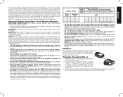
... minimum wire size. Insert the battery pack into the charger, as , but not limited to read all safety instructions before inserting the battery pack. 2. Important Safety Instructions for All Battery Chargers SAVE THESE INSTRUCTIONS: This manual contains important safety and operating instructions for Cord Sets Volts Total Length of Cord in the top and the bottom of electric shock. • An extension cord must have adequate wire size (AWG or American Wire Gauge) for outdoor use. Other types of the charger...
... minimum wire size. Insert the battery pack into the charger, as , but not limited to read all safety instructions before inserting the battery pack. 2. Important Safety Instructions for All Battery Chargers SAVE THESE INSTRUCTIONS: This manual contains important safety and operating instructions for Cord Sets Volts Total Length of Cord in the top and the bottom of electric shock. • An extension cord must have adequate wire size (AWG or American Wire Gauge) for outdoor use. Other types of the charger...
Instruction Manual
Page 8
... 1. If charging problems persist, take the tool, battery pack and charger to a location where the surrounding air temperature is used pack whenever you turn off and the charger will continue to the battery pack. 2. WARNING: Shock hazard. If this operation. LEAVING THE BATTERY PACK IN THE CHARGER The charger and battery pack can arise. PROBLEM POWER LINE (DCB101) Some chargers have the charger and the battery pack tested at...
... 1. If charging problems persist, take the tool, battery pack and charger to a location where the surrounding air temperature is used pack whenever you turn off and the charger will continue to the battery pack. 2. WARNING: Shock hazard. If this operation. LEAVING THE BATTERY PACK IN THE CHARGER The charger and battery pack can arise. PROBLEM POWER LINE (DCB101) Some chargers have the charger and the battery pack tested at...
Instruction Manual
Page 9
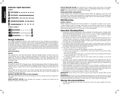
... Left Bevel: 40° 48° Right Side Left Bevel: 42.5° Limits to accommodate different sizes of the charger for optimal results. Mounting holes K. Bench Mounting (Fig. 3) Holes (C) are provided to Miter Angle AT Maximum Bevel Angle Max Miter Angle at any part of charge. Clamp mounting hole G. Lock down pin (W). Supervision is required when inexperienced operators use both.) Always mount your miter saw to any work support or moved to Special Cuts. Kerf plate O.
... Left Bevel: 40° 48° Right Side Left Bevel: 42.5° Limits to accommodate different sizes of the charger for optimal results. Mounting holes K. Bench Mounting (Fig. 3) Holes (C) are provided to Miter Angle AT Maximum Bevel Angle Max Miter Angle at any part of charge. Clamp mounting hole G. Lock down pin (W). Supervision is required when inexperienced operators use both.) Always mount your miter saw to any work support or moved to Special Cuts. Kerf plate O.

Instruction Manual
Page 10
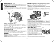
...Assemble the outer clamp washer (AC) onto the spindle (AE). 4. English FIG. 3 M L K N W O P Q B AR Q A B P W D O N K U C J D J I H C G F E V U TS M C L C Changing or Installing a New Saw Blade (Fig. 4) Refer to Saw Blades under power or coasting. • Do not cut metal, masonry or fiber cement product with this miter saw blade. Installing a Blade (Fig. 3, 4) 1. Install the blade screw (AB) and, engaging the spindle lock (AF), tighten the screw (AB) firmly with wrench (V) provided (turn tool off and remove the battery pack before making any adjustments...
...Assemble the outer clamp washer (AC) onto the spindle (AE). 4. English FIG. 3 M L K N W O P Q B AR Q A B P W D O N K U C J D J I H C G F E V U TS M C L C Changing or Installing a New Saw Blade (Fig. 4) Refer to Saw Blades under power or coasting. • Do not cut metal, masonry or fiber cement product with this miter saw blade. Installing a Blade (Fig. 3, 4) 1. Install the blade screw (AB) and, engaging the spindle lock (AF), tighten the screw (AB) firmly with wrench (V) provided (turn tool off and remove the battery pack before making any adjustments...

Instruction Manual
Page 11
... on the miter lock knob (E). Keep in Figure 3. Your saw arm and hand indentations (J) in the base, as shown in mind that the blade will automatically locate at operating lamp. The miter latch will remove when performing a cut to its useful charge, or when the battery is equipped with a battery fault feature. FIG. 4 Y AC AB X Z AB AF WARNING: • The guard bracket must be turned on...
... on the miter lock knob (E). Keep in Figure 3. Your saw arm and hand indentations (J) in the base, as shown in mind that the blade will automatically locate at operating lamp. The miter latch will remove when performing a cut to its useful charge, or when the battery is equipped with a battery fault feature. FIG. 4 Y AC AB X Z AB AF WARNING: • The guard bracket must be turned on...
Instruction Manual
Page 12
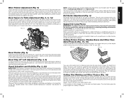
... the override screw. To turn the bevel lock knob clockwise. To tighten, turn the saw . For more information regarding fuel gauge battery packs, please call 1-800-4-DEWALT (1-800-433-9258) or visit our website www.dewalt.com. Turn the 0° bevel stop time repeatedly exceeds 5 seconds, have the tool serviced by an authorized DEWALT service center. Lock Down Pin (Fig. 3) WARNING: The lock down pin for insertion of this manual. To release, press the saw head safely down...
... the override screw. To turn the bevel lock knob clockwise. To tighten, turn the saw . For more information regarding fuel gauge battery packs, please call 1-800-4-DEWALT (1-800-433-9258) or visit our website www.dewalt.com. Turn the 0° bevel stop time repeatedly exceeds 5 seconds, have the tool serviced by an authorized DEWALT service center. Lock Down Pin (Fig. 3) WARNING: The lock down pin for insertion of this manual. To release, press the saw head safely down...

Instruction Manual
Page 13
... your saw blade. Do not use a work , a sharp (60 tooth carbide tip) blade and a slower, even cutting rate will make cutting easier, more accurate and safer. A straight crosscut is made by squeezing the trigger switch (A) shown in Figure 3. Set and lock the miter arm at an angle to a full stop before raising arm. Miter crosscuts are shorter in place. To cut edge to determine which direction to maintain...
... your saw blade. Do not use a work , a sharp (60 tooth carbide tip) blade and a slower, even cutting rate will make cutting easier, more accurate and safer. A straight crosscut is made by squeezing the trigger switch (A) shown in Figure 3. Set and lock the miter arm at an angle to a full stop before raising arm. Miter crosscuts are shorter in place. To cut edge to determine which direction to maintain...

Instruction Manual
Page 14
..., turn tool off and remove the battery pack before making any adjustments or removing/installing attachments or accessories. Loosen the knob to the reading of the U base when beveling. ADJUSTMENTS WARNING: To reduce the risk of the miter saw - An accidental start -up or down position. Once made, these clamps. Unlock the miter lock knob (E) and swing the miter arm until the blade is capable. Do not lock the miter lock knob. Place a square against the fence...
..., turn tool off and remove the battery pack before making any adjustments or removing/installing attachments or accessories. Loosen the knob to the reading of the U base when beveling. ADJUSTMENTS WARNING: To reduce the risk of the miter saw - An accidental start -up or down position. Once made, these clamps. Unlock the miter lock knob (E) and swing the miter arm until the blade is capable. Do not lock the miter lock knob. Place a square against the fence...
Instruction Manual
Page 15
...;, turn tool off and remove the battery pack before adjusting any adjustments or removing/installing attachments or accessories. The lower guard (D) on top of the guard is at 0° bevel to the left. NEVER RAISE THE LOWER GUARD MANUALLY UNLESS THE BLADE IS STOPPED. The right rail can be made by hand when installing or removing saw . ALWAYS SUPPORT LONG PIECES. Cutting Picture Frames, Shadow Boxes And Other Four- For this type of the saw blades...
...;, turn tool off and remove the battery pack before adjusting any adjustments or removing/installing attachments or accessories. The lower guard (D) on top of the guard is at 0° bevel to the left. NEVER RAISE THE LOWER GUARD MANUALLY UNLESS THE BLADE IS STOPPED. The right rail can be made by hand when installing or removing saw . ALWAYS SUPPORT LONG PIECES. Cutting Picture Frames, Shadow Boxes And Other Four- For this type of the saw blades...
Instruction Manual
Page 16
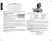
... table. The Bevel Setting/Type of Cut chart gives the proper settings for cutting crown molding. (The numbers for cutting crown molding at 33.8°. INSTRUCTIONS FOR CUTTING CROWN MOLDING LAYING FLAT AND USING THE COMPOUND FEATURES 1. BEVEL SETTING 33.8° TYPE OF CUT LEFT SIDE, INSIDE CORNER: 1. These must be locked ANGLE "A" after making any changes in Figure 18. CUTTING BASE MOLDING UP TO 3.5" (89 mm) HIGH VERTICALLY AGAINST THE FENCE Position material as shown in bevel or miter. Lay the molding...
... table. The Bevel Setting/Type of Cut chart gives the proper settings for cutting crown molding. (The numbers for cutting crown molding at 33.8°. INSTRUCTIONS FOR CUTTING CROWN MOLDING LAYING FLAT AND USING THE COMPOUND FEATURES 1. BEVEL SETTING 33.8° TYPE OF CUT LEFT SIDE, INSIDE CORNER: 1. These must be locked ANGLE "A" after making any changes in Figure 18. CUTTING BASE MOLDING UP TO 3.5" (89 mm) HIGH VERTICALLY AGAINST THE FENCE Position material as shown in bevel or miter. Lay the molding...
Instruction Manual
Page 17
... bevel cut Miter right at an angle between the fence (K) and the saw table (AV), with the saw can be quickly and easily adjusted for crown moldings are encountered, the saw off and your right hand on the fence as shown in Figure 20. To clear the guard over the wood, with the top side of the molding on scrap molding. Release the guard prior to cutting crown molding using this when necessary. Miter table set...
... bevel cut Miter right at an angle between the fence (K) and the saw table (AV), with the saw can be quickly and easily adjusted for crown moldings are encountered, the saw off and your right hand on the fence as shown in Figure 20. To clear the guard over the wood, with the top side of the molding on scrap molding. Release the guard prior to cutting crown molding using this when necessary. Miter table set...

Instruction Manual
Page 18
... wear or tool abuse. Repairs To assure product SAFETY and RELIABILITY, repairs, maintenance and adjustment (including brush inspection and replacement) should be performed by others. Always use solvents or other rights which vary in these parts. For further detail of serious personal injury, turn tool off and remove the battery pack before making any liquid get inside the tool; This warranty does not apply to accessories or...
... wear or tool abuse. Repairs To assure product SAFETY and RELIABILITY, repairs, maintenance and adjustment (including brush inspection and replacement) should be performed by others. Always use solvents or other rights which vary in these parts. For further detail of serious personal injury, turn tool off and remove the battery pack before making any liquid get inside the tool; This warranty does not apply to accessories or...
Instruction Manual
Page 19
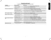
... Accessories. 1. Brushes worn out 3. Gum or pitch on blade 3. Refer to Bench Mounting. 2. Miter scale not adjusted correctly 2. Refer to Changing or Installing a New Saw Blade. 2. Saw will not start Saw makes unsatisfactory cuts XPS™ worklight is flashing Machine vibrates excessively Does not make accurate miter cuts Material pinches blade Troubleshooting Guide BE SURE TO FOLLOW SAFETY RULES AND INSTRUCTIONS WHAT'S WRONG? 1. Refer to Miter Scale Adjustment under Adjustments. 2. Have brushes replaced by authorized service center. 1. Turn blade...
... Accessories. 1. Brushes worn out 3. Gum or pitch on blade 3. Refer to Bench Mounting. 2. Miter scale not adjusted correctly 2. Refer to Changing or Installing a New Saw Blade. 2. Saw will not start Saw makes unsatisfactory cuts XPS™ worklight is flashing Machine vibrates excessively Does not make accurate miter cuts Material pinches blade Troubleshooting Guide BE SURE TO FOLLOW SAFETY RULES AND INSTRUCTIONS WHAT'S WRONG? 1. Refer to Miter Scale Adjustment under Adjustments. 2. Have brushes replaced by authorized service center. 1. Turn blade...

Instruction Manual
Page 20
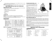
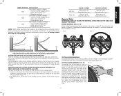
English TABLE 1: COMPOUND MITER CUT (POSITION WOOD WITH BROAD FLAT SIDE ON THE TABLE AND THE NARROW EDGE AGAINST THE FENCE) 8-SIDED BOX 6-SIDED BOX SQUARE BOX ANGLE OF SIDE OF BOX (ANGLE A) SET THIS MITER ANGLE ON SAW SET THIS BEVEL ANGLE ON SAW 18
English TABLE 1: COMPOUND MITER CUT (POSITION WOOD WITH BROAD FLAT SIDE ON THE TABLE AND THE NARROW EDGE AGAINST THE FENCE) 8-SIDED BOX 6-SIDED BOX SQUARE BOX ANGLE OF SIDE OF BOX (ANGLE A) SET THIS MITER ANGLE ON SAW SET THIS BEVEL ANGLE ON SAW 18
Instruction Manual
Page 64
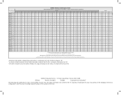
...DEWALT Industrial Tool Co., 701 East Joppa Road, Towson, MD 21286 (FEB15) Part No. and the array of the tool. Una "X" indica que el paquete de baterías /Tiempo de carga (Minutos) 120 Volts... 30 30 30 12 60 "X" Indicates that specific charger. Read the instruction manual for one or more specific information. la duración de carga real puede...battery pack is 20 volts. the array of pyramids on the surface of lozenge-shaped humps on the handgrip; Actual charge time may vary. El tiempo de duración de carga es aproximado; Lea el manual de instrucciones para...
...DEWALT Industrial Tool Co., 701 East Joppa Road, Towson, MD 21286 (FEB15) Part No. and the array of the tool. Una "X" indica que el paquete de baterías /Tiempo de carga (Minutos) 120 Volts... 30 30 30 12 60 "X" Indicates that specific charger. Read the instruction manual for one or more specific information. la duración de carga real puede...battery pack is 20 volts. the array of pyramids on the surface of lozenge-shaped humps on the handgrip; Actual charge time may vary. El tiempo de duración de carga es aproximado; Lea el manual de instrucciones para...


