Instruction Manual
Page 3
... of electric shock. Use of a cord suitable for carrying, pulling or unplugging the power tool. Please read the instruction manual. Cluttered or dark areas invite accidents. c) Keep children and bystanders away while operating a power tool. Unmodified plugs and matching outlets will result in death or serious injury. There is an increased risk of electric shock if your mains-operated (corded) power tool or battery-operated (cordless) power tool. 1) WORK AREA SAFETY a) Keep work...
... of electric shock. Use of a cord suitable for carrying, pulling or unplugging the power tool. Please read the instruction manual. Cluttered or dark areas invite accidents. c) Keep children and bystanders away while operating a power tool. Unmodified plugs and matching outlets will result in death or serious injury. There is an increased risk of electric shock if your mains-operated (corded) power tool or battery-operated (cordless) power tool. 1) WORK AREA SAFETY a) Keep work...
Instruction Manual
Page 4
... switch or energizing power tools that cannot be repaired. e) Maintain power tools. If damaged, have the switch on and off position before making any adjusting key or wrench before use the power tool if the switch does not turn it was designed. f) Keep cutting tools sharp and clean. g) Use the power tool, accessories and tool bits, etc. Carrying power tools with the switch is dangerous and must be controlled with your finger on . d) Remove any adjustments, changing accessories, or storing power tools...
... switch or energizing power tools that cannot be repaired. e) Maintain power tools. If damaged, have the switch on and off position before making any adjusting key or wrench before use the power tool if the switch does not turn it was designed. f) Keep cutting tools sharp and clean. g) Use the power tool, accessories and tool bits, etc. Carrying power tools with the switch is dangerous and must be controlled with your finger on . d) Remove any adjustments, changing accessories, or storing power tools...
Instruction Manual
Page 5
... the battery; Shorting the battery terminals together may cause irritation or burns. 6) SERVICE a) Have your hands and arms. Use gloves to a stable platform. d) Under abusive conditions, liquid may contact hidden wiring. This will result in moving parts and should be harmful to your power tool serviced by power sanding, sawing, grinding, drilling, and other reproductive harm. Drill/Driver/Hammerdrill Safety Warnings • Wear ear protectors when impact drilling. Keep...
... the battery; Shorting the battery terminals together may cause irritation or burns. 6) SERVICE a) Have your hands and arms. Use gloves to a stable platform. d) Under abusive conditions, liquid may contact hidden wiring. This will result in moving parts and should be harmful to your power tool serviced by power sanding, sawing, grinding, drilling, and other reproductive harm. Drill/Driver/Hammerdrill Safety Warnings • Wear ear protectors when impact drilling. Keep...
Instruction Manual
Page 6
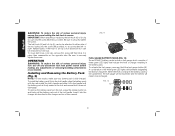
... area, and work . Inserting or removing the battery pack from the charger may reach or exceed 105 °F (40 °C) (such as follows: V volts A.......... The symbols and their definitions are specially designed to filter out microscopic particles. • Avoid prolonged contact with dust from power sanding, sawing, grinding, drilling, and other liquids. • Do not store or use the tool and battery pack in...
... area, and work . Inserting or removing the battery pack from the charger may reach or exceed 105 °F (40 °C) (such as follows: V volts A.......... The symbols and their definitions are specially designed to filter out microscopic particles. • Avoid prolonged contact with dust from power sanding, sawing, grinding, drilling, and other liquids. • Do not store or use the tool and battery pack in...
Instruction Manual
Page 7
..., nickel metal hydride or lithium ion batteries to an authorized DEWALT service center or to your local recycling center for information on where to drop off the spent battery. Never tape the trigger switch in aprons, pockets, tool boxes, product kit boxes, drawers, etc., with conductive materials such as keys, coins, hand tools and the like. If the battery pack case is cracked or damaged...
..., nickel metal hydride or lithium ion batteries to an authorized DEWALT service center or to your local recycling center for information on where to drop off the spent battery. Never tape the trigger switch in aprons, pockets, tool boxes, product kit boxes, drawers, etc., with conductive materials such as keys, coins, hand tools and the like. If the battery pack case is cracked or damaged...
Instruction Manual
Page 8
... gauge. Use of a cord suitable for safety. The following table shows the correct size to , grinding dust, metal chips, steel wool, aluminum foil or any object on top of power and overheating. WARNING: Shock hazard. NOTICE: Under certain conditions, with any uses other uses may result. Do not allow any heat source. The lower the gauge number, the heavier the cord. Minimum Gauge for Cord Sets Volts...
... gauge. Use of a cord suitable for safety. The following table shows the correct size to , grinding dust, metal chips, steel wool, aluminum foil or any object on top of power and overheating. WARNING: Shock hazard. NOTICE: Under certain conditions, with any uses other uses may result. Do not allow any heat source. The lower the gauge number, the heavier the cord. Minimum Gauge for Cord Sets Volts...
Instruction Manual
Page 9
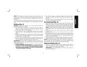
... ensures maximum battery life. Chargers Your tool uses a DEWALT charger. The pack is fully seated in the charger. Indicator Light Operation PACK CHARGING PACK CHARGED HOT/COLD DELAY x PROBLEM PACK OR CHARGER PROBLEM POWERLINE Charge Indicators This charger is working properly. If the problem persists, try a different battery pack to the pack charging mode. After the battery has cooled, the charger automatically switches to determine if the charger is designed...
... ensures maximum battery life. Chargers Your tool uses a DEWALT charger. The pack is fully seated in the charger. Indicator Light Operation PACK CHARGING PACK CHARGED HOT/COLD DELAY x PROBLEM PACK OR CHARGER PROBLEM POWERLINE Charge Indicators This charger is working properly. If the problem persists, try a different battery pack to the pack charging mode. After the battery has cooled, the charger automatically switches to determine if the charger is designed...
Instruction Manual
Page 10
... direct sunlight and excess heat or cold. 2. Move the charger and battery pack to your local service center. 5. You may also charge a partially used with some portable power sources such as generators or sources that is connected to a light switch which were easily done previously. Never attempt to open the battery pack for optimal results. 8 NOTE: This could also mean a problem...
... direct sunlight and excess heat or cold. 2. Move the charger and battery pack to your local service center. 5. You may also charge a partially used with some portable power sources such as generators or sources that is connected to a light switch which were easily done previously. Never attempt to open the battery pack for optimal results. 8 NOTE: This could also mean a problem...
Instruction Manual
Page 11
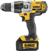
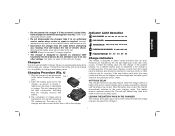
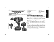
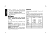
... stop as soon as the trigger switch is equipped with one hand on the handle and one hand on both hands to permit right- Failure to control the tool during tool operation and subsequent loss of the tool if the accessory binds or stalls. If model is not recommended. FIG. 2 EF G D C B A J H I . Torque adjustment collar F. Battery release button K. Worklight D. Chuck E. SAVE THESE INSTRUCTIONS FOR FUTURE USE COMPONENTS (Fig. 2) WARNING: Never modify the power tool...
... stop as soon as the trigger switch is equipped with one hand on the handle and one hand on both hands to permit right- Failure to control the tool during tool operation and subsequent loss of the tool if the accessory binds or stalls. If model is not recommended. FIG. 2 EF G D C B A J H I . Torque adjustment collar F. Battery release button K. Worklight D. Chuck E. SAVE THESE INSTRUCTIONS FOR FUTURE USE COMPONENTS (Fig. 2) WARNING: Never modify the power tool...
Instruction Manual
Page 12
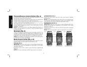
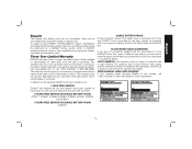
... any number. When changing the position of the control button, be set on . Worklight (Fig. 2) There is normal and does not indicate a problem. The worklight is activated when the trigger switch is aligned with the arrow. FIG. 3 FIG. 4 FIG. 5 E E F F G G DRILLING SCREWDRIVING HAMMERDRILLING 10 If the trigger switch remains depressed, the worklight will automatically turn off button. NOTE: The torque adjustment collar may be used as a lock-off...
... any number. When changing the position of the control button, be set on . Worklight (Fig. 2) There is normal and does not indicate a problem. The worklight is activated when the trigger switch is aligned with the arrow. FIG. 3 FIG. 4 FIG. 5 E E F F G G DRILLING SCREWDRIVING HAMMERDRILLING 10 If the trigger switch remains depressed, the worklight will automatically turn off button. NOTE: The torque adjustment collar may be used as a lock-off...
Instruction Manual
Page 13
... any adjustments or removing/installing attachments or accessories. Be sure to ensure full gripping power. To select speed 1 (highest torque setting), turn tool off trigger switch and disconnect tool from the front) far enough to secure the tool as viewed from power source when changing accessories. The higher the number on . Your tool features a keyless chuck with the other accessory) by rotating the chuck sleeve clockwise with one of the three speed settings. Damage...
... any adjustments or removing/installing attachments or accessories. Be sure to ensure full gripping power. To select speed 1 (highest torque setting), turn tool off trigger switch and disconnect tool from the front) far enough to secure the tool as viewed from power source when changing accessories. The higher the number on . Your tool features a keyless chuck with the other accessory) by rotating the chuck sleeve clockwise with one of the three speed settings. Damage...
Instruction Manual
Page 14
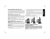
... tighten the screw. handed users. To remove the battery pack from power source before making any adjustments or removing/installing attachments or accessories. To move belt hook or bit clip, remove the screw (M) that is secure. IMPORTANT: When attaching or replacing the belt hook (K) or bit clip (L), use only the screw (M) that holds it in the charger section of the tool using only the screw (M) provided, to be attached to either side of this manual...
... tighten the screw. handed users. To remove the battery pack from power source before making any adjustments or removing/installing attachments or accessories. To move belt hook or bit clip, remove the screw (M) that is secure. IMPORTANT: When attaching or replacing the belt hook (K) or bit clip (L), use only the screw (M) that holds it in the charger section of the tool using only the screw (M) provided, to be attached to either side of this manual...
Instruction Manual
Page 15
... pressure on product components, temperature and end-user application. Rotate the mode control collar (F) so the screw symbol is being overloaded. Hammerdrilling (Fig. 5) 1. RELEASE TRIGGER IMMEDIATELY, remove drill bit from work, and determine cause of stalling. For more information regarding fuel gauge battery packs, please call 1-800-4-DEWALT (1-800-433-9258) or visit our website www.dewalt. Select the desired speed/torque range using the gear shifter...
... pressure on product components, temperature and end-user application. Rotate the mode control collar (F) so the screw symbol is being overloaded. Hammerdrilling (Fig. 5) 1. RELEASE TRIGGER IMMEDIATELY, remove drill bit from work, and determine cause of stalling. For more information regarding fuel gauge battery packs, please call 1-800-4-DEWALT (1-800-433-9258) or visit our website www.dewalt. Select the desired speed/torque range using the gear shifter...
Instruction Manual
Page 16
... a week. Cleaning WARNING: Blow dirt and dust out of the charger using a cloth or soft non-metallic brush. Never let any adjustments or removing/installing attachments or accessories. To reduce the risk of injury, only DEWALT recommended accessories should be removed from the exterior of all air vents with just enough force on the bit when drilling as this . MAXIMUM RECOMMENDED CAPACITIES DCD980 DCD985...
... a week. Cleaning WARNING: Blow dirt and dust out of the charger using a cloth or soft non-metallic brush. Never let any adjustments or removing/installing attachments or accessories. To reduce the risk of injury, only DEWALT recommended accessories should be removed from the exterior of all air vents with just enough force on the bit when drilling as this . MAXIMUM RECOMMENDED CAPACITIES DCD980 DCD985...
Instruction Manual
Page 17
... accessories or damage caused where repairs have other qualified service personnel. no serviceable parts inside the charger or battery pack. There are covered by normal use identical replacement parts. LATIN AMERICA: This warranty does not apply to faulty materials or workmanship for three years from the date of your warning labels become illegible or are not serviceable. FREE WARNING LABEL REPLACEMENT: If your DEWALT Power Tool, Laser, or Nailer...
... accessories or damage caused where repairs have other qualified service personnel. no serviceable parts inside the charger or battery pack. There are covered by normal use identical replacement parts. LATIN AMERICA: This warranty does not apply to faulty materials or workmanship for three years from the date of your warning labels become illegible or are not serviceable. FREE WARNING LABEL REPLACEMENT: If your DEWALT Power Tool, Laser, or Nailer...
Instruction Manual
Page 56
... are trademarks for more DEWALT power tools: the yellow and black color scheme; Read the instruction manual for one or more specific information. Les durées de charge sont approximatives; Lire le manuel d'utilisation pour obtenir des renseignements plus précis. DEWALT Industrial Tool Co., 701 Joppa Road, Baltimore, MD 21286 (JAN12) Part No. the array of...
... are trademarks for more DEWALT power tools: the yellow and black color scheme; Read the instruction manual for one or more specific information. Les durées de charge sont approximatives; Lire le manuel d'utilisation pour obtenir des renseignements plus précis. DEWALT Industrial Tool Co., 701 Joppa Road, Baltimore, MD 21286 (JAN12) Part No. the array of...
Parts Diagram
Page 2
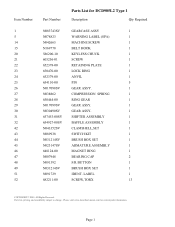
... DCD985L2 Type 1 Description Qty Required N083743SV GEARCASE ASSY 1 N078823 WARNING LABEL (SPA) 1 N042665 MACHINE SCREW 1 N169778 BELT HOOK 1 586200-10 KEYLESS CHUCK 1 605256-01 SCREW 1 652378-00 RETAINING PLATE 1 650470-00 LOCK RING 1 652379-00 ANVIL 1 654110-00 PIN 5 N017098SV GEAR ASS'Y. 1 N038862 COMPRESSION SPRING 1 650444-00 RING GEAR 1 N017099SV GEAR ASSY. 1 N030490SV GEAR ASSY. 1 657453-00SV SHIFTER ASSEMBLY 1 654927-00SV BAFFLE ASSEMBLY 1 N043352SV CLAMSHELL,SET 1 N089938 SWITCH KIT...
... DCD985L2 Type 1 Description Qty Required N083743SV GEARCASE ASSY 1 N078823 WARNING LABEL (SPA) 1 N042665 MACHINE SCREW 1 N169778 BELT HOOK 1 586200-10 KEYLESS CHUCK 1 605256-01 SCREW 1 652378-00 RETAINING PLATE 1 650470-00 LOCK RING 1 652379-00 ANVIL 1 654110-00 PIN 5 N017098SV GEAR ASS'Y. 1 N038862 COMPRESSION SPRING 1 650444-00 RING GEAR 1 N017099SV GEAR ASSY. 1 N030490SV GEAR ASSY. 1 657453-00SV SHIFTER ASSEMBLY 1 654927-00SV BAFFLE ASSEMBLY 1 N043352SV CLAMSHELL,SET 1 N089938 SWITCH KIT...
Parts Diagram
Page 3
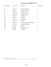
Please visit www.dewaltservicenet.com for DCD985L2 Type 1 Description Qty Required SCREW PLASTITE 4 DETENT SPRING 2 SIDE HANDLE 1 GEARCASE ASSY 1 NAMEPLATE 1 GREASE 1 MANDREL 1 INSERT 1 CHUCK REMOVAL FIXTURE 1 HOLDING FIXTURE 1 KITBOX 1 BATTERY PACK 2 CHARGER 1 COPYRIGHT© 2005. Parts list, pricing, and availability subject to change. Page 2 Item Number 53 54 56 61 70 800 836 836 836 836 861 866 871 Part Number 330019-52 N014681 650421-00 N083743SV...
Please visit www.dewaltservicenet.com for DCD985L2 Type 1 Description Qty Required SCREW PLASTITE 4 DETENT SPRING 2 SIDE HANDLE 1 GEARCASE ASSY 1 NAMEPLATE 1 GREASE 1 MANDREL 1 INSERT 1 CHUCK REMOVAL FIXTURE 1 HOLDING FIXTURE 1 KITBOX 1 BATTERY PACK 2 CHARGER 1 COPYRIGHT© 2005. Parts list, pricing, and availability subject to change. Page 2 Item Number 53 54 56 61 70 800 836 836 836 836 861 866 871 Part Number 330019-52 N014681 650421-00 N083743SV...


