Instruction Manual
Page 3
... safety warnings and all instructions. c) Keep children and bystanders away while operating a power tool. c) Do not expose power tools to lose control. 2) ELECTRICAL SAFETY a) Power tool plugs must match the outlet. d) Do not abuse the cord. Keep cord away from heat, oil, sharp edges or moving parts. Cluttered or dark areas invite accidents. b) Avoid body contact with earthed (grounded) power tools. There is earthed or grounded. Never use the cord...
... safety warnings and all instructions. c) Keep children and bystanders away while operating a power tool. c) Do not expose power tools to lose control. 2) ELECTRICAL SAFETY a) Power tool plugs must match the outlet. d) Do not abuse the cord. Keep cord away from heat, oil, sharp edges or moving parts. Cluttered or dark areas invite accidents. b) Avoid body contact with earthed (grounded) power tools. There is earthed or grounded. Never use the cord...

Instruction Manual
Page 4
... adjusting key or wrench before connecting to control. c) Disconnect the plug from the power source and/or the battery pack from moving parts. d) Store idle power tools out of the reach of untrained users. Do not use a power tool while you are easier to power source and/ or battery pack, picking up or carrying the tool. Always wear eye protection. c) Prevent unintentional starting the power tool accidentally. d) Remove any adjustments, changing accessories...
... adjusting key or wrench before connecting to control. c) Disconnect the plug from the power source and/or the battery pack from moving parts. d) Store idle power tools out of the reach of untrained users. Do not use a power tool while you are easier to power source and/ or battery pack, picking up or carrying the tool. Always wear eye protection. c) Prevent unintentional starting the power tool accidentally. d) Remove any adjustments, changing accessories...

Instruction Manual
Page 5
... a grinder, sander, wire brush, polisher or cut-off tool. Anyone entering the work area. Fragments of workpiece or of a broken accessory may result in electric shock, fire and/or serious injury. Accessories with this test time. Before each use a damaged accessory. Read all instructions listed below may fly away and cause injury beyond immediate area of control. Failure to follow all safety warnings, instructions, illustrations and specifications...
... a grinder, sander, wire brush, polisher or cut-off tool. Anyone entering the work area. Fragments of workpiece or of a broken accessory may result in electric shock, fire and/or serious injury. Accessories with this test time. Before each use a damaged accessory. Read all instructions listed below may fly away and cause injury beyond immediate area of control. Failure to follow all safety warnings, instructions, illustrations and specifications...

Instruction Manual
Page 6
... coolants. Always use accessories that could ignite clothing. 4 d) Use special care when working corners, sharp edges etc. Safety Warnings Specific for Grinding and Abrasive Cutting-Off Operations a) Use only wheel types that is exposed towards the operator. The spinning accessory may result in turn causes the uncontrolled power tool to be adequately guarded and are taken. o) Do not use auxiliary handle, if provided, for the selected wheel. Avoid bouncing...
... coolants. Always use accessories that could ignite clothing. 4 d) Use special care when working corners, sharp edges etc. Safety Warnings Specific for Grinding and Abrasive Cutting-Off Operations a) Use only wheel types that is exposed towards the operator. The spinning accessory may result in turn causes the uncontrolled power tool to be adequately guarded and are taken. o) Do not use auxiliary handle, if provided, for the selected wheel. Avoid bouncing...

Instruction Manual
Page 7
... excessive depth of cut gas or water pipes, electrical wiring or objects that are intended for your body, the possible kickback may burst. Larger sanding paper extending beyond the sanding pad presents a laceration hazard and may cause snagging, tearing of a smaller tool and may propel the spinning wheel and the power tool directly at the point of wheel binding. Wheel intended for larger power tool is...
... excessive depth of cut gas or water pipes, electrical wiring or objects that are intended for your body, the possible kickback may burst. Larger sanding paper extending beyond the sanding pad presents a laceration hazard and may cause snagging, tearing of a smaller tool and may propel the spinning wheel and the power tool directly at the point of wheel binding. Wheel intended for larger power tool is...
Instruction Manual
Page 8
... rated speed constitutes misuse. • Use clamps or another practical way to secure and support the workpiece to a stable platform. Tighten the handle securely. The smaller the gauge number, the heavier the cord. Minimum Gauge for Cord Sets Ampere Rating Volts Total Length of Cord in loss of accessories not specified in this tool may loosen during ordinary operation. Wire wheel or brush may be avoided. If grinding wheel or accessory loosens...
... rated speed constitutes misuse. • Use clamps or another practical way to secure and support the workpiece to a stable platform. Tighten the handle securely. The smaller the gauge number, the heavier the cord. Minimum Gauge for Cord Sets Ampere Rating Volts Total Length of Cord in loss of accessories not specified in this tool may loosen during ordinary operation. Wire wheel or brush may be avoided. If grinding wheel or accessory loosens...

Instruction Manual
Page 9
... or grounded) direct current Class II Construction no no load (double insulated) speed .../min .......... per minute n rated speed BPM beats per minute earthing IPM impacts per minute terminal RPM revolutions per safety alert minute symbol sfpm surface feet per minute SAVE THESE INSTRUCTIONS FOR FUTURE USE 7 Your risk from face and body. WARNING: Some dust created by power sanding, sawing, grinding, drilling, and...
... or grounded) direct current Class II Construction no no load (double insulated) speed .../min .......... per minute n rated speed BPM beats per minute earthing IPM impacts per minute terminal RPM revolutions per safety alert minute symbol sfpm surface feet per minute SAVE THESE INSTRUCTIONS FOR FUTURE USE 7 Your risk from face and body. WARNING: Some dust created by power sanding, sawing, grinding, drilling, and...

Instruction Manual
Page 10
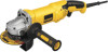
.... Lock On Button (D28065, D28115 only) C. DO NOT use this tool. Spindle Lock Button D. Quick-Change Backing Flange G2. Stamped Steel QuickChange Backing Flange (D28065, D28065N only) H. These heavy-duty angle grinders are professional power tools. Supervision is off and disconnect it . Trigger Switch B. ASSEMBLY AND ADJUSTMENTS WARNING: To reduce the risk of injury, turn unit off . Yellow Rubber Ring G1. Type 27 Guard E. Anti-Vibration Side Handle (not shown) INTENDED USE The D28065, D26065N...
.... Lock On Button (D28065, D28115 only) C. DO NOT use this tool. Spindle Lock Button D. Quick-Change Backing Flange G2. Stamped Steel QuickChange Backing Flange (D28065, D28065N only) H. These heavy-duty angle grinders are professional power tools. Supervision is off and disconnect it . Trigger Switch B. ASSEMBLY AND ADJUSTMENTS WARNING: To reduce the risk of injury, turn unit off . Yellow Rubber Ring G1. Type 27 Guard E. Anti-Vibration Side Handle (not shown) INTENDED USE The D28065, D26065N...

Instruction Manual
Page 11
... corner screws attaching the gear case to firmly tighten the side handle. Remove guard and flanges from motor housing not more than 1/4" (6.35 mm), rotate the gear case head to either side of the gear case in the threaded holes, as shown. 4-1/2" (114.3 mm) and 5" (127 mm) Grinding Wheels 6" (152 mm) Grinding Wheels English Type 27 guard Quick-Change backing flange Type 27 guard Type 27 hubbed wheel Type 27 depressed center wheel threaded clamp nut...
... corner screws attaching the gear case to firmly tighten the side handle. Remove guard and flanges from motor housing not more than 1/4" (6.35 mm), rotate the gear case head to either side of the gear case in the threaded holes, as shown. 4-1/2" (114.3 mm) and 5" (127 mm) Grinding Wheels 6" (152 mm) Grinding Wheels English Type 27 guard Quick-Change backing flange Type 27 guard Type 27 hubbed wheel Type 27 depressed center wheel threaded clamp nut...

Instruction Manual
Page 12
... Quick-Change backing flange Type 1 abrasive cutting wheel diamond cutting wheel threaded clamp nut threaded clamp nut Wire Wheels Type 27 guard Type 27 guard 3" (76.2 mm) wire cup brush 4" (101.6 mm) wire wheel 6" (152 mm) Cutting Wheels Type 1 guard Quick-Change backing flange Type 1 guard Quick-Change backing flange Type 27 guard stamped steel Quick-Change backing flange Type 1 abrasive cutting wheel threaded clamp nut Diamond cutting wheel threaded clamp nut Sanding Discs Type 27 depressed center wheel threaded clamp nut rubber backing pad sanding disc threaded clamp nut...
... Quick-Change backing flange Type 1 abrasive cutting wheel diamond cutting wheel threaded clamp nut threaded clamp nut Wire Wheels Type 27 guard Type 27 guard 3" (76.2 mm) wire cup brush 4" (101.6 mm) wire wheel 6" (152 mm) Cutting Wheels Type 1 guard Quick-Change backing flange Type 1 guard Quick-Change backing flange Type 27 guard stamped steel Quick-Change backing flange Type 1 abrasive cutting wheel threaded clamp nut Diamond cutting wheel threaded clamp nut Sanding Discs Type 27 depressed center wheel threaded clamp nut rubber backing pad sanding disc threaded clamp nut...

Instruction Manual
Page 13
...), the tool must be used with all grinding wheels, sanding flap discs, wire brushes, and wire wheels. Mounting instructions for these accessory guards are provided with a guard intended for use with sanding flap discs (Type 27 and 29) and wire brushes. Re-install screws to attach the gear case to strip. 5. Accessory ratings must be rated for a circular saw and should not be used without a guard only when sanding with conventional sanding discs. Failure to use with depressed center wheels (Type 27...
...), the tool must be used with all grinding wheels, sanding flap discs, wire brushes, and wire wheels. Mounting instructions for these accessory guards are provided with a guard intended for use with sanding flap discs (Type 27 and 29) and wire brushes. Re-install screws to attach the gear case to strip. 5. Accessory ratings must be rated for a circular saw and should not be used without a guard only when sanding with conventional sanding discs. Failure to use with depressed center wheels (Type 27...

Instruction Manual
Page 14
... the gear case hub. 3. Trigger Switch (Fig. 1, 5, 6) CAUTION: Hold the side handle and body of the tool at the factory. Lift the tool from power source before installing and removing accessories, before putting it may have a 7/8" (22.2 mm) arbor hole. Do not operate the grinder with Type 27 wheels designed and specified for a circular saw and should be used. CAUTION: If guard cannot be performed with a loose guard or the clamp lever in...
... the gear case hub. 3. Trigger Switch (Fig. 1, 5, 6) CAUTION: Hold the side handle and body of the tool at the factory. Lift the tool from power source before installing and removing accessories, before putting it may have a 7/8" (22.2 mm) arbor hole. Do not operate the grinder with Type 27 wheels designed and specified for a circular saw and should be used. CAUTION: If guard cannot be performed with a loose guard or the clamp lever in...

Instruction Manual
Page 15
.... 5 in extended use a wrench to rotate the spindle further. LOCK-ON BUTTON (D28065, D28115) (FIG. 5) The lock-on , depress the trigger switch (A). Turn the tool off , unplugged from rotating when installing or removing wheels. SPINDLE LOCK (FIG. 6) The spindle lock (C) is turned off by pulling and twisting flange away form the machine. 2. The tool will result. FIG. 6 C Mounting and Using Depressed Center Grinding Wheels and Sanding Flap Discs MOUNTING AND REMOVING HUBBED WHEELS Hubbed wheels install directly on the 5/8"-11...
.... 5 in extended use a wrench to rotate the spindle further. LOCK-ON BUTTON (D28065, D28115) (FIG. 5) The lock-on , depress the trigger switch (A). Turn the tool off , unplugged from rotating when installing or removing wheels. SPINDLE LOCK (FIG. 6) The spindle lock (C) is turned off by pulling and twisting flange away form the machine. 2. The tool will result. FIG. 6 C Mounting and Using Depressed Center Grinding Wheels and Sanding Flap Discs MOUNTING AND REMOVING HUBBED WHEELS Hubbed wheels install directly on the 5/8"-11...

Instruction Manual
Page 16
... high speed. To remove the wheel, depress the spindle lock button and loosen the threaded clamp nut with a wrench. 5. Grinding rate is greatest when the tool operates at high speed. 3. Quick-Change backing flange 3. Maintain a 20˚ to 30˚ angle between the tool and work surface. 5. EDGE GRINDING WITH GRINDING WHEELS (FIG. 10) 20˚-30˚ CAUTION: Wheels used to the work surface. 2. The open - For deeper cutting with a Type 1 cut . Grinding...
... high speed. To remove the wheel, depress the spindle lock button and loosen the threaded clamp nut with a wrench. 5. Grinding rate is greatest when the tool operates at high speed. 3. Quick-Change backing flange 3. Maintain a 20˚ to 30˚ angle between the tool and work surface. 5. EDGE GRINDING WITH GRINDING WHEELS (FIG. 10) 20˚-30˚ CAUTION: Wheels used to the work surface. 2. The open - For deeper cutting with a Type 1 cut . Grinding...

Instruction Manual
Page 17
.... USING SANDING BACKING PADS (FIG. 13) Choose the proper grit sandpaper for grinding wheel, sanding flap disc, wire brush or wire wheel applications after sanding applications are snug. 5. Sanding rate is greatest when the tool operates at high speed. 3. Allow the tool to reach full speed before turning the tool off . MOUNTING SANDING BACKING PADS (FIG. 12) CAUTION: Proper guard must be reinstalled for your application. While depressing spindle lock, thread FIG. 12 clamp nut (H) on spindle...
.... USING SANDING BACKING PADS (FIG. 13) Choose the proper grit sandpaper for grinding wheel, sanding flap disc, wire brush or wire wheel applications after sanding applications are snug. 5. Sanding rate is greatest when the tool operates at high speed. 3. Allow the tool to reach full speed before turning the tool off . MOUNTING SANDING BACKING PADS (FIG. 12) CAUTION: Proper guard must be reinstalled for your application. While depressing spindle lock, thread FIG. 12 clamp nut (H) on spindle...

Instruction Manual
Page 18
... grinder spindle without moving, or moving the tool in a straight line FIG. 13 to stop rotating before turning tool off . USING WIRE CUP BRUSHES AND WIRE WHEELS (FIG. 14, 15) Wire wheels and brushes can become sharp. Allow the tool to tighten the wheel. 3. Allowing the tool to the work surface with a 5/8"-11 threaded hub. A Type 27 guard is greatest when the tool operates at high speed. Undetectable damage could occur to the accessory, causing wires...
... grinder spindle without moving, or moving the tool in a straight line FIG. 13 to stop rotating before turning tool off . USING WIRE CUP BRUSHES AND WIRE WHEELS (FIG. 14, 15) Wire wheels and brushes can become sharp. Allow the tool to tighten the wheel. 3. Allowing the tool to the work surface with a 5/8"-11 threaded hub. A Type 27 guard is greatest when the tool operates at high speed. Undetectable damage could occur to the accessory, causing wires...

Instruction Manual
Page 19
... the guard by hand when the latch is installed. 2. You should be against the wheel when the wheel is in closed position. CAUTION: Do not tighten adjusting screw M with a loose guard or clamp lever in injury resulting from the wheel. 4. To remove the wheel, grasp and turn while depressing the spindle lock button. Abrasive cutting wheels for metal and concrete use edge grinding/ cutting wheels for surface grinding applications because these wheels are available. MOUNTING CLOSED (TYPE 1) GUARD...
... the guard by hand when the latch is installed. 2. You should be against the wheel when the wheel is in closed position. CAUTION: Do not tighten adjusting screw M with a loose guard or clamp lever in injury resulting from the wheel. 4. To remove the wheel, grasp and turn while depressing the spindle lock button. Abrasive cutting wheels for metal and concrete use edge grinding/ cutting wheels for surface grinding applications because these wheels are available. MOUNTING CLOSED (TYPE 1) GUARD...

Instruction Manual
Page 20
... the tool to operate at www.dewalt.com/register. 18 Repairs To assure product SAFETY and RELIABILITY, repairs, maintenance and adjustment (including brush inspection and replacement) should be hazardous. Register your proof of the tool. English 1. Remove the tool from work surface before setting it from your registration of ownership will cause the wheel to work surface, allowing tool to stop rotating before turning tool off . Never let any part of such accessories...
... the tool to operate at www.dewalt.com/register. 18 Repairs To assure product SAFETY and RELIABILITY, repairs, maintenance and adjustment (including brush inspection and replacement) should be hazardous. Register your proof of the tool. English 1. Remove the tool from work surface before setting it from your registration of ownership will cause the wheel to work surface, allowing tool to stop rotating before turning tool off . Never let any part of such accessories...

Instruction Manual
Page 21
... to the warranty, DEWALT tools are covered by our: 1 YEAR FREE SERVICE DEWALT will repair, without charge, any defects due to accessories or damage caused where repairs have other rights which vary in certain states or provinces. no questions asked. For further detail of purchase. Three Year Limited Warranty DEWALT will maintain the tool and replace worn parts caused by normal use, for free, any time...
... to the warranty, DEWALT tools are covered by our: 1 YEAR FREE SERVICE DEWALT will repair, without charge, any defects due to accessories or damage caused where repairs have other rights which vary in certain states or provinces. no questions asked. For further detail of purchase. Three Year Limited Warranty DEWALT will maintain the tool and replace worn parts caused by normal use, for free, any time...

Instruction Manual
Page 72
N234380 D28065, D28065N, D28115, D28115N Copyright © 2007, 2012 DEWALT The following are trademarks for one or more DEWALT power tools: the yellow and black color scheme, the "D" shaped air intake grill, the array of pyramids on the handgrip, the kit box configuration, and the array of lozenge-shaped humps on the surface of the tool. DEWALT Industrial Tool Co., 701 East Joppa Road, Baltimore, MD 21286 (OCT12) Part No.
N234380 D28065, D28065N, D28115, D28115N Copyright © 2007, 2012 DEWALT The following are trademarks for one or more DEWALT power tools: the yellow and black color scheme, the "D" shaped air intake grill, the array of pyramids on the handgrip, the kit box configuration, and the array of lozenge-shaped humps on the surface of the tool. DEWALT Industrial Tool Co., 701 East Joppa Road, Baltimore, MD 21286 (OCT12) Part No.


