Owners Manual
Page 1
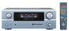
Be sure to offer, read these instructions carefully and use the set properly. PLEASE RECORD UNIT SERIAL NUMBER ATTACHED TO THE REAR OF THE CABINET FOR FUTURE REFERENCE" "SERIAL NO. IN MASTER VOLUME 2 We greatly appreciate your purchase of the AVR-2805/985. 2 To be sure you take maximum advantage of all the features the AVR-2805/985 has to keep this manual for future reference, should any questions or problems arise. AV SURROUND RECEIVER AVR-2805/985 OPERATING INSTRUCTIONS FUNCTION SOURCE TUNING PRESET ZONE 2 / REC SELECT VIDEO SELECT ON / STANDBY MODE ANALOG EXT.
Be sure to offer, read these instructions carefully and use the set properly. PLEASE RECORD UNIT SERIAL NUMBER ATTACHED TO THE REAR OF THE CABINET FOR FUTURE REFERENCE" "SERIAL NO. IN MASTER VOLUME 2 We greatly appreciate your purchase of the AVR-2805/985. 2 To be sure you take maximum advantage of all the features the AVR-2805/985 has to keep this manual for future reference, should any questions or problems arise. AV SURROUND RECEIVER AVR-2805/985 OPERATING INSTRUCTIONS FUNCTION SOURCE TUNING PRESET ZONE 2 / REC SELECT VIDEO SELECT ON / STANDBY MODE ANALOG EXT.
Owners Manual
Page 4
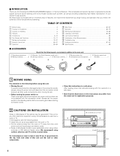
...;7 Additional Information 87~97 ⁄8 Specifications 98 2 ACCESSORIES Check that there are included in addition to the main unit: q Operating instructions.......1 w Warranty ( for choosing the DENON AVR-2805/985 Digital A / V Surround Receiver. For heat dispersal, leave at least 4 inch/10 cm of space between all other components. 4 inch/10 cm or more 4 inch/10...
...;7 Additional Information 87~97 ⁄8 Specifications 98 2 ACCESSORIES Check that there are included in addition to the main unit: q Operating instructions.......1 w Warranty ( for choosing the DENON AVR-2805/985 Digital A / V Surround Receiver. For heat dispersal, leave at least 4 inch/10 cm of space between all other components. 4 inch/10 cm or more 4 inch/10...
Owners Manual
Page 5
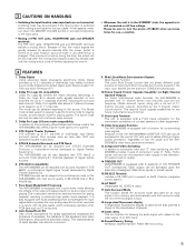
...the speakers, and other -set-up -converting video signals. Pure Direct Mode/AL24 Processing The AVR-2805/985 is connected to the input jacks. DTS 96/24 compatibility The AVR-2805/985 can be played in extremely high quality music playback. Auto Setup/Room EQ Use of the ...jack and SPEAKER terminals The PRE OUT jacks, HEADPHONE jack and SPEAKER terminals include a muting circuit. Because of this, the AVR-2805/985's MONITOR OUT jack can thus be used for several seconds after the muting circuit stops functioning. Multi Zone Music Entertainment System Multi...
...the speakers, and other -set-up -converting video signals. Pure Direct Mode/AL24 Processing The AVR-2805/985 is connected to the input jacks. DTS 96/24 compatibility The AVR-2805/985 can be played in extremely high quality music playback. Auto Setup/Room EQ Use of the ...jack and SPEAKER terminals The PRE OUT jacks, HEADPHONE jack and SPEAKER terminals include a muting circuit. Because of this, the AVR-2805/985's MONITOR OUT jack can thus be used for several seconds after the muting circuit stops functioning. Multi Zone Music Entertainment System Multi...
Owners Manual
Page 7
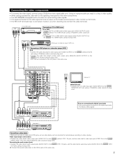
... IN OUT IN AUDIO VIDEO Note on connecting the digital input jacks • Only audio signals are two sets of the other components. • The AVR-2805/985 is equipped with a function for simultaneous recording or video copying. Connecting the audio output jacks • Connect the video deck's audio output jacks (AUDIO OUT...
... IN OUT IN AUDIO VIDEO Note on connecting the digital input jacks • Only audio signals are two sets of the other components. • The AVR-2805/985 is equipped with a function for simultaneous recording or video copying. Connecting the audio output jacks • Connect the video deck's audio output jacks (AUDIO OUT...
Owners Manual
Page 8
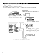
... the S-VIDEO VCR-2 OUT jack using a S-Video connection cord. • VDP can be connected to the VDP jacks in conjunction with each other. • The AVR-2805/985 is equipped with a function for converting video signals. • The signal connected to the S-Video signal terminal is also possible to connect a video disc player...
... the S-VIDEO VCR-2 OUT jack using a S-Video connection cord. • VDP can be connected to the VDP jacks in conjunction with each other. • The AVR-2805/985 is equipped with a function for converting video signals. • The signal connected to the S-Video signal terminal is also possible to connect a video disc player...
Owners Manual
Page 9
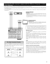
... a commercially available video stabilizer, etc., with Color Difference (Component - Connecting the video component equipped with a TBC (time base corrector) function between the AVR-2805/985 and the VTR, or if your VTR has a TBC function, turn it on. (Video jack) (Video jack) 9 For details, see "Setting ...input jacks (COMPONENT VIDEO INPUT) to the operating instructions of sync or not display at the system setup. MONITOR OUT jacks The AVR-2805/985 is not possible, so when not using the component video monitor output terminal connect the player using 75 Ω/ohms coaxial video ...
... a commercially available video stabilizer, etc., with Color Difference (Component - Connecting the video component equipped with a TBC (time base corrector) function between the AVR-2805/985 and the VTR, or if your VTR has a TBC function, turn it on. (Video jack) (Video jack) 9 For details, see "Setting ...input jacks (COMPONENT VIDEO INPUT) to the operating instructions of sync or not display at the system setup. MONITOR OUT jacks The AVR-2805/985 is not possible, so when not using the component video monitor output terminal connect the player using 75 Ω/ohms coaxial video ...
Owners Manual
Page 18
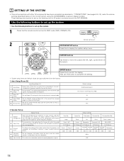
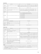
... Use the following buttons to set up the system • Use the following buttons to set up the listening room's AV system centered around the AVR-2805/985. Default settings SURROUND BACK All Channel and Frequency=0dB All OFF Mic 2. Large Small Yes Small Small / 2spkrs Front L & R Center Subwoofer Surround...different channels in order to obtain optimum effects. 4 Crossover Frequency Set the frequency (Hz) below on the monitor screen using the AVR-2805/985's on the screen ENTER button Press this to switch the display. Also use for Mic or V.Aux Lchannel input jack. Auto Setup...
... Use the following buttons to set up the system • Use the following buttons to set up the listening room's AV system centered around the AVR-2805/985. Default settings SURROUND BACK All Channel and Frequency=0dB All OFF Mic 2. Large Small Yes Small Small / 2spkrs Front L & R Center Subwoofer Surround...different channels in order to obtain optimum effects. 4 Crossover Frequency Set the frequency (Hz) below on the monitor screen using the AVR-2805/985's on the screen ENTER button Press this to switch the display. Also use for Mic or V.Aux Lchannel input jack. Auto Setup...
Owners Manual
Page 19
.... A setting to the S-VIDEO MONITOR OUT jack. (For details, see page 49.) • The AVR-2805/985's on-screen display function is connected to both the AVR-2805/985's S-Video and video monitor output jacks and signals are input to the AVR-2805/985 from the monitor output terminal. AUX - - This assigns the color difference (component) video input jacks...
.... A setting to the S-VIDEO MONITOR OUT jack. (For details, see page 49.) • The AVR-2805/985's on-screen display function is connected to both the AVR-2805/985's S-Video and video monitor output jacks and signals are input to the AVR-2805/985 from the monitor output terminal. AUX - - This assigns the color difference (component) video input jacks...
Owners Manual
Page 32
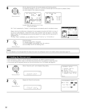
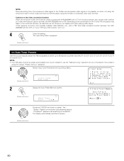
... directly from the speakers to adjust the level. • The level can select the unit of "1ft (0.1m)" or "0.1ft (0.01m)". 7 Enter the setting. The AVR-2805/985 automatically sets the optimum surround delay time for "Default", the settings are reset to the factory default values (see page 68.) 1 Select "Channel Level" at...
... directly from the speakers to adjust the level. • The level can select the unit of "1ft (0.1m)" or "0.1ft (0.01m)". 7 Enter the setting. The AVR-2805/985 automatically sets the optimum surround delay time for "Default", the settings are reset to the factory default values (see page 68.) 1 Select "Channel Level" at...
Owners Manual
Page 37
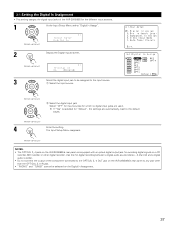
...for digital recording between a digital audio source (stereo - 2 channel) and a digital audio recorder. • Do not connect the output of the AVR-2805/985 for recording digital signals on a CD recorder, MD recorder or other than the OPTICAL 3, 4 IN jack. • "PHONO" and "TUNER" cannot... be assigned to the input source. The Input Setup Menu reappears. (Remote control unit) NOTES: • The OPTICAL 3, 4 jacks on the AVR-2805/985's rear panel are used. 3-1 Setting the Digital In Assignment • This setting assigns the digital input jacks of the component connected to the OPTICAL...
...for digital recording between a digital audio source (stereo - 2 channel) and a digital audio recorder. • Do not connect the output of the AVR-2805/985 for recording digital signals on a CD recorder, MD recorder or other than the OPTICAL 3, 4 IN jack. • "PHONO" and "TUNER" cannot... be assigned to the input source. The Input Setup Menu reappears. (Remote control unit) NOTES: • The OPTICAL 3, 4 jacks on the AVR-2805/985's rear panel are used. 3-1 Setting the Digital In Assignment • This setting assigns the digital input jacks of the component connected to the OPTICAL...
Owners Manual
Page 38
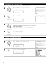
... In Assign • This setting assigns the color difference (component) video input jacks of the player being used. Select according to the specifications of the AVR-2805/985 for the different input sources. 1 Select "Component In Assign" at the Input Setup Menu. (Remote control unit) *Input Setup Ext.In SW Lev. 2 Display to...
... In Assign • This setting assigns the color difference (component) video input jacks of the player being used. Select according to the specifications of the AVR-2805/985 for the different input sources. 1 Select "Component In Assign" at the Input Setup Menu. (Remote control unit) *Input Setup Ext.In SW Lev. 2 Display to...
Owners Manual
Page 40
... conversion function: When the component video terminals are used to connect the AVR-2805/985 with a TV (or monitor, projector, etc.) and the video (yellow) or S video terminals are used to connect the AVR-2805/985 with a TBC (time base corrector) function between the AVR2805/985 and the VTR, or if your VTR has a TBC function, turn...
... conversion function: When the component video terminals are used to connect the AVR-2805/985 with a TV (or monitor, projector, etc.) and the video (yellow) or S video terminals are used to connect the AVR-2805/985 with a TBC (time base corrector) function between the AVR2805/985 and the VTR, or if your VTR has a TBC function, turn...
Owners Manual
Page 47
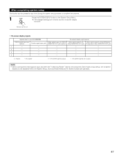
The changed settings are entered and the on-screen display turns off. (Remote control unit) • On-screen display signals Signals input to the AVR-2805/985 On-screen display signal output VIDEO signal input jack (yellow) S-video signal input jack Video signal output to VIDEO MONITOR OUT jack (yellow) Video signal ...
The changed settings are entered and the on-screen display turns off. (Remote control unit) • On-screen display signals Signals input to the AVR-2805/985 On-screen display signal output VIDEO signal input jack (yellow) S-video signal input jack Video signal output to VIDEO MONITOR OUT jack (yellow) Video signal ...
Owners Manual
Page 48
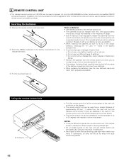
...soon as possible.) • When inserting the batteries, be used to operate not only the AVR-2805/985 but this depends on the frequency of usage. • Even if less than a year has...can be operated at the remote sensor. • The remote control unit can be used to operate non-Denon remote control compatible products. NOTES: • It may result in malfunction, so keep the set . ... to operate the remote control unit if the remote sensor is only for other remote control compatible DENON components as possible. w Set three R6P/AA batteries in the battery compartment in the way or...
...soon as possible.) • When inserting the batteries, be used to operate not only the AVR-2805/985 but this depends on the frequency of usage. • Even if less than a year has...can be operated at the remote sensor. • The remote control unit can be used to operate non-Denon remote control compatible products. NOTES: • It may result in malfunction, so keep the set . ... to operate the remote control unit if the remote sensor is only for other remote control compatible DENON components as possible. w Set three R6P/AA batteries in the battery compartment in the way or...
Owners Manual
Page 59
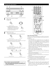
... (Remote control unit) (Main unit) • Selecting the external input (EXT. The presence or absence of playback and while searching during DTS playback in the AVR-2805/985's surround decoder is detected, the signals input to the analog input. q AUTO (auto mode) In this mode to switch the external input. Note that noise...
... (Remote control unit) (Main unit) • Selecting the external input (EXT. The presence or absence of playback and while searching during DTS playback in the AVR-2805/985's surround decoder is detected, the signals input to the analog input. q AUTO (auto mode) In this mode to switch the external input. Note that noise...
Owners Manual
Page 62
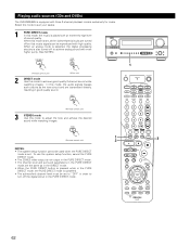
... processing circuitry is also turned off to achieve analog sound with an extremely high level of sound quality. Playing audio sources (CDs and DVDs) The AVR-2805/985 is equipped with high quality. To use the system setup function, cancel the PURE DIRECT mode. • The ZONE2 video output is not output in...
... processing circuitry is also turned off to achieve analog sound with an extremely high level of sound quality. Playing audio sources (CDs and DVDs) The AVR-2805/985 is equipped with high quality. To use the system setup function, cancel the PURE DIRECT mode. • The ZONE2 video output is not output in...
Owners Manual
Page 65
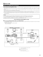
... (DENON RC-616, 617 or 618) is wired and connected between the MAIN ZONE and ZONE2, the remote-controllable devices in such a way that device's remote control unit or preset a separately sold devices, refer to the devices' operating instructions. • When the PURE DIRECT mode is set to 13. 65 The AVR-2805/985...
... (DENON RC-616, 617 or 618) is wired and connected between the MAIN ZONE and ZONE2, the remote-controllable devices in such a way that device's remote control unit or preset a separately sold devices, refer to the devices' operating instructions. • When the PURE DIRECT mode is set to 13. 65 The AVR-2805/985...

Owners Manual
Page 66
Using this case, Surround Back PREOUT and speaker out cannot be used for MAIN ZONE. • The AVR-2805/985 is equipped with preout terminals for which the volume is adjustable (ZONE2) and speaker out terminals for which the volume is selected at System Setup ...
Using this case, Surround Back PREOUT and speaker out cannot be used for MAIN ZONE. • The AVR-2805/985 is equipped with preout terminals for which the volume is adjustable (ZONE2) and speaker out terminals for which the volume is selected at System Setup ...

Owners Manual
Page 70
... CH OUT" surround parameter is set to "ON", and the PLII mode is set when this parameter is set up to "1spkr" or "2spkrs"). The AVR-2805/985 sets the mode automatically according to the previous screen. 6 Set the various surround parameters. Display *Surr Parameter MODE: PLII C (Pro LogicII Cinema mode) *Surr Parameter...
... CH OUT" surround parameter is set to "ON", and the PLII mode is set when this parameter is set up to "1spkr" or "2spkrs"). The AVR-2805/985 sets the mode automatically according to the previous screen. 6 Set the various surround parameters. Display *Surr Parameter MODE: PLII C (Pro LogicII Cinema mode) *Surr Parameter...
Owners Manual
Page 76
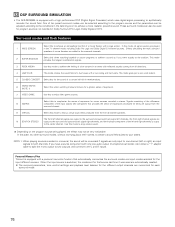
... a concert hall rich in an arena with only one channel (left or right), so input signals to both channels. 12 DSP SURROUND SIMULATION • The AVR-2805/985 is output to the center channel. Signals consisting of the difference component of a live house with a low ceiling and hard walls. In this to emphasize...
... a concert hall rich in an arena with only one channel (left or right), so input signals to both channels. 12 DSP SURROUND SIMULATION • The AVR-2805/985 is output to the center channel. Signals consisting of the difference component of a live house with a low ceiling and hard walls. In this to emphasize...

