
Owners Manual
Page 6
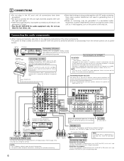
... sure to SURR. RL R L L R RL CD player or other component equipped with right). • Insert the plugs securely. For details, see "Setting the Trigger Out Setup" on and off for optical connections, removing the cap before connecting. Connecting the AC OUTLETS Turntable (MM cartridge) Connecting a turntable Connect the turntable's output cord...
... sure to SURR. RL R L L R RL CD player or other component equipped with right). • Insert the plugs securely. For details, see "Setting the Trigger Out Setup" on and off for optical connections, removing the cap before connecting. Connecting the AC OUTLETS Turntable (MM cartridge) Connecting a turntable Connect the turntable's output cord...
Owners Manual
Page 9
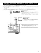
... VIDEO-1 IN jack using 75 Ω/ohms coaxial video pin-plug cords. • The color difference input jacks may be changed at the system setup. Y, PR/CR, PB/CB) Video jacks • When making connections, also refer to the operating instructions of the other component. 9 For ...outputs are labeled Y, CB, CR, or Y, Pb, Pr, or Y, R-Y, B-Y. For details, see "Setting the video In Assignment" on page 24. • The AVR-2803's on some TVs, monitors or video components ("CR, CB and Y", "RY, B-Y and Y", "Pr, Pb and Y", etc.). Connecting the video component equipped with the TV...
... VIDEO-1 IN jack using 75 Ω/ohms coaxial video pin-plug cords. • The color difference input jacks may be changed at the system setup. Y, PR/CR, PB/CB) Video jacks • When making connections, also refer to the operating instructions of the other component. 9 For ...outputs are labeled Y, CB, CR, or Y, Pb, Pr, or Y, R-Y, B-Y. For details, see "Setting the video In Assignment" on page 24. • The AVR-2803's on some TVs, monitors or video components ("CR, CB and Y", "RY, B-Y and Y", "Pr, Pb and Y", etc.). Connecting the video component equipped with the TV...
Owners Manual
Page 15
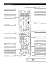
... (MAIN) buttons 47) Tuner system/System buttons 32, 35, 47, 61~63) MODE SELECT button 32) System buttons 32, 34, 35, 38) SYSTEM SETUP/SETUP button 17, 30, 34) Cursor buttons 16) ON SCREEN/DISPLAY button ....(34, 35, 46) TEST TONE button 49) SYSTEM CALL buttons 37) USE/LEARN button... FRONT SPEAKER button 41) SURROUND BACK button 53) INPUT MODE selector buttons 42, 44) NOTE: • The shaded button do not function with the AVR-2803/983. (Nothing happens when they are pressed.) 15 Remote control unit • For details on the functions of these parts, refer to the pages given...
... (MAIN) buttons 47) Tuner system/System buttons 32, 35, 47, 61~63) MODE SELECT button 32) System buttons 32, 34, 35, 38) SYSTEM SETUP/SETUP button 17, 30, 34) Cursor buttons 16) ON SCREEN/DISPLAY button ....(34, 35, 46) TEST TONE button 49) SYSTEM CALL buttons 37) USE/LEARN button... FRONT SPEAKER button 41) SURROUND BACK button 53) INPUT MODE selector buttons 42, 44) NOTE: • The shaded button do not function with the AVR-2803/983. (Nothing happens when they are pressed.) 15 Remote control unit • For details on the functions of these parts, refer to the pages given...
Owners Manual
Page 16
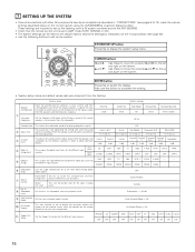
...Surround Back Sp. AUX - - OFF Surround Back Variable Subwoofer = +15 dB Auto Surround Mode = ON On Screen Display = ON !1 Trigger Out Setup Set the Trigger Out output for optimizing the timing with other AV components have been completed as described in "CONNECTIONS" (see page 63). • Use...system and their corresponding sizes (Small for regular speakers, Large for zone 2. Set the frequency (Hz) below on the monitor screen using the AVR-2803/983's on-screen display function. Use these to move the cursors (• and ª) to the up the listening room's AV system ...
...Surround Back Sp. AUX - - OFF Surround Back Variable Subwoofer = +15 dB Auto Surround Mode = ON On Screen Display = ON !1 Trigger Out Setup Set the Trigger Out output for optimizing the timing with other AV components have been completed as described in "CONNECTIONS" (see page 63). • Use...system and their corresponding sizes (Small for regular speakers, Large for zone 2. Set the frequency (Hz) below on the monitor screen using the AVR-2803/983's on-screen display function. Use these to move the cursors (• and ª) to the up the listening room's AV system ...

Owners Manual
Page 17
...systems and a television monitor: Subwoofer Center speaker system Surround back speaker systems Front speaker systems Set these at a system setup setting, you can be changed up , connect the AVR-2803/983's MONITOR OUT connector with the monitor TV and turn on connecting the monitor TV, see page 30.) •... The AVR-2803/983's on-screen display function is completed, press the system setup button again. A1 ~ A8 B1 ~ B8 C1 ~ C8 D1 ~ D8 E1 ~ E8 Default settings 87.5/89...
...systems and a television monitor: Subwoofer Center speaker system Surround back speaker systems Front speaker systems Set these at a system setup setting, you can be changed up , connect the AVR-2803/983's MONITOR OUT connector with the monitor TV and turn on connecting the monitor TV, see page 30.) •... The AVR-2803/983's on-screen display function is completed, press the system setup button again. A1 ~ A8 B1 ~ B8 C1 ~ C8 D1 ~ D8 E1 ~ E8 Default settings 87.5/89...
Owners Manual
Page 18
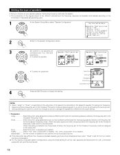
...set for the Crossover Frequency mode. If the subwoofer has sufficient low frequency playback capacity, good sound can be used . 1 At the System Setup Menu select "Speaker Configuration". 2 Switch to the speaker configuration screen. 3 Set whether or not speakers are connected and, if so, their ...for the Crossover Frequency mode. Setting the type of speakers • Set up in function of your speaker systems. Performing this setup optimizes the system. • The composition of the signals output to the different channels and the frequency response are adjusted automatically ...
...set for the Crossover Frequency mode. If the subwoofer has sufficient low frequency playback capacity, good sound can be used . 1 At the System Setup Menu select "Speaker Configuration". 2 Switch to the speaker configuration screen. 3 Set whether or not speakers are connected and, if so, their ...for the Crossover Frequency mode. Setting the type of speakers • Set up in function of your speaker systems. Performing this setup optimizes the system. • The composition of the signals output to the different channels and the frequency response are adjusted automatically ...
Owners Manual
Page 19
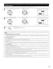
... played from the subwoofer channel are LFE signals (during Dolby Digital or DTS signal playback) and the channel specified as "Small" in the setup menu. For details, refer to "YES", the low frequency portion is output from those channels. - Select the setting. 3 Enter the setting...the actual volume of the low frequency range. • Selection of the "LFE " play mode will play mode that channel only. The System Setup Menu reappears. When using small speakers, however, setting the crossover frequency to a high frequency may result in surround modes other than Dolby/DTS....
... played from the subwoofer channel are LFE signals (during Dolby Digital or DTS signal playback) and the channel specified as "Small" in the setup menu. For details, refer to "YES", the low frequency portion is output from those channels. - Select the setting. 3 Enter the setting...the actual volume of the low frequency range. • Selection of the "LFE " play mode will play mode that channel only. The System Setup Menu reappears. When using small speakers, however, setting the crossover frequency to a high frequency may result in surround modes other than Dolby/DTS....

Owners Manual
Page 20
... the distances between subwoofer and listening position FL Center FR Subwoofer L1 L2 L5 Listening position SL L3 L4 SR SBL SBR 1 At the System Setup Menu select "Delay Time". 2 Switch to the Delay Time screen. 3 Select the desired unit, meters or feet. Example: When "Feet" is selected in step 3, the...
... the distances between subwoofer and listening position FL Center FR Subwoofer L1 L2 L5 Listening position SL L3 L4 SR SBL SBR 1 At the System Setup Menu select "Delay Time". 2 Switch to the Delay Time screen. 3 Select the desired unit, meters or feet. Example: When "Feet" is selected in step 3, the...

Owners Manual
Page 21
The AVR-2803/983 automatically sets the optimum surround delay time for "Default", the settings are reset to the measured distance. If you set , the settings are automatically ... the remote control unit. (For details, see page 16, 17). Select the value closest to the factory default values (see page 49.) 1 At the System Setup Menu select "Channel Level". 2 Switch to the default values. The distance changes in highlighted line. 7 Enter the setting. The System...
The AVR-2803/983 automatically sets the optimum surround delay time for "Default", the settings are reset to the measured distance. If you set , the settings are automatically ... the remote control unit. (For details, see page 16, 17). Select the value closest to the factory default values (see page 49.) 1 At the System Setup Menu select "Channel Level". 2 Switch to the default values. The distance changes in highlighted line. 7 Enter the setting. The System...
Owners Manual
Page 23
...NOTES: • The OPTICAL 4 jacks on the AVR-2803/983's rear panel to the default values. 4 Enter the setting. After you have completed the SYSTEM SETUP CHANNEL LEVEL adjustments, you adjust the channel levels while in the SYSTEM SETUP CHANNEL LEVEL mode, the channel level adjustments made will... all surround modes. Setting the Digital In Assignment • This setting assigns the digital input jacks of the AVR-2803/983 for the different input sources. 1 At the System Setup Menu select "Digital In Assignment". 2 Switch to the Digital Inputs screen. 3 Select the digital input jack...
...NOTES: • The OPTICAL 4 jacks on the AVR-2803/983's rear panel to the default values. 4 Enter the setting. After you have completed the SYSTEM SETUP CHANNEL LEVEL adjustments, you adjust the channel levels while in the SYSTEM SETUP CHANNEL LEVEL mode, the channel level adjustments made will... all surround modes. Setting the Digital In Assignment • This setting assigns the digital input jacks of the AVR-2803/983 for the different input sources. 1 At the System Setup Menu select "Digital In Assignment". 2 Switch to the Digital Inputs screen. 3 Select the digital input jack...

Owners Manual
Page 24
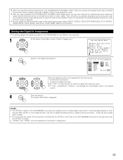
When the default, "Yes", is compressed automatically according to the combination of the AVR-2803/983 for the different input sources. 1 At the System Setup Menu select "Video In Assignment". 2 Switch to the Video In Assignment screen. 3 Select the component (Y, PB/CB and PR/CR) video ... the Video In Assignment • This setting assigns the color difference (component) video input jacks of speakers being used . Setting the Dolby Digital Setup Sets the down-mixing method when not using a center speaker or surround speakers, the sound is not to be assigned to "ON". q Input...
When the default, "Yes", is compressed automatically according to the combination of the AVR-2803/983 for the different input sources. 1 At the System Setup Menu select "Video In Assignment". 2 Switch to the Video In Assignment screen. 3 Select the component (Y, PB/CB and PR/CR) video ... the Video In Assignment • This setting assigns the color difference (component) video input jacks of speakers being used . Setting the Dolby Digital Setup Sets the down-mixing method when not using a center speaker or surround speakers, the sound is not to be assigned to "ON". q Input...

Owners Manual
Page 25
BACK/ZONE2 PREOUT" terminals. 1 At the System Setup Menu select "Zone2 Control" and press the ENTER button. 2 The "Zone2 Control" screen appears. When...to use as Zone 2 out. At the "Zone2 Control" screen, select "Exit" and press the ENTER button. The System Setup Menu reappears. [2] Setting the Zone2 vol. Setting the ZONE2 Control [1] Setting the power amplifier assignment Make this setting to switch ... setting. level Set the Zone 2 pre-out output level adjustment. 1 At the System Setup Menu select "Zone2 Control" and press the ENTER button. 25 3 Enter the setting. The System...
BACK/ZONE2 PREOUT" terminals. 1 At the System Setup Menu select "Zone2 Control" and press the ENTER button. 2 The "Zone2 Control" screen appears. When...to use as Zone 2 out. At the "Zone2 Control" screen, select "Exit" and press the ENTER button. The System Setup Menu reappears. [2] Setting the Zone2 vol. Setting the ZONE2 Control [1] Setting the power amplifier assignment Make this setting to switch ... setting. level Set the Zone 2 pre-out output level adjustment. 1 At the System Setup Menu select "Zone2 Control" and press the ENTER button. 25 3 Enter the setting. The System...

Owners Manual
Page 26
.... 0 dB, -40 dB: The output level is fixed at the set level and the volume can be adjusted. 4 Enter the setting. The System Setup Menu reappears. Select according to the specifications of the analog input signal connected to the Ext.In Subwoofer. 1 At the System... refer to the Ext.In Subwoofer Level screen. 3 Select the desired setting. Level" and press the ENTER button. 3 Select the desired setting. The System Setup Menu reappears. 26 In Subwoofer Level • Set the method of playback of the player being used. Setting the Ext. At the "Zone2 Control" screen...
.... 0 dB, -40 dB: The output level is fixed at the set level and the volume can be adjusted. 4 Enter the setting. The System Setup Menu reappears. Select according to the specifications of the analog input signal connected to the Ext.In Subwoofer. 1 At the System... refer to the Ext.In Subwoofer Level screen. 3 Select the desired setting. Level" and press the ENTER button. 3 Select the desired setting. The System Setup Menu reappears. 26 In Subwoofer Level • Set the method of playback of the player being used. Setting the Ext. At the "Zone2 Control" screen...
Owners Manual
Page 27
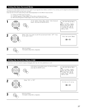
The System Setup Menu reappears. 27 Setting the Auto Surround Mode The surround mode used at last for the different...use it is also stored separately for the three types of Dolby Digital, DTS or other multi-channel format 1 At the System Setup Menu select "Auto Surround Mode" and press the ENTER button. 2 Select "ON" if you do not want to turn the...On Screen Display" and press the ENTER button. 2 Select "ON" or "OFF". 3 Enter the setting. The System Setup Menu reappears. q Analog and PCM 2-channel signals w 2-channel signals of Dolby Digital, DTS or other than the menu ...
The System Setup Menu reappears. 27 Setting the Auto Surround Mode The surround mode used at last for the different...use it is also stored separately for the three types of Dolby Digital, DTS or other multi-channel format 1 At the System Setup Menu select "Auto Surround Mode" and press the ENTER button. 2 Select "ON" if you do not want to turn the...On Screen Display" and press the ENTER button. 2 Select "ON" or "OFF". 3 Enter the setting. The System Setup Menu reappears. q Analog and PCM 2-channel signals w 2-channel signals of Dolby Digital, DTS or other than the menu ...

Owners Manual
Page 28
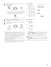
...to automatically search for the different input sources. 1 At the System Setup Menu select "Trigger Out Setup". 2 Switch to the Trigger Out Setup screen. 3 Select the input source and select "ON" or "OFF". 4 Enter the setting. The System Setup Menu reappears. NOTE: • If an FM station cannot be...station, then preset it using the manual "Preset memory" operation. 1 At the System Setup Menu select "Auto Tuner Presets". 2 Switch to the Auto Preset Memory screen. 28 Setting the Trigger Out Setup • Sets the Trigger Out output for FM broadcasts and store up to 40 ...
...to automatically search for the different input sources. 1 At the System Setup Menu select "Trigger Out Setup". 2 Switch to the Trigger Out Setup screen. 3 Select the input source and select "ON" or "OFF". 4 Enter the setting. The System Setup Menu reappears. NOTE: • If an FM station cannot be...station, then preset it using the manual "Preset memory" operation. 1 At the System Setup Menu select "Auto Tuner Presets". 2 Switch to the Auto Preset Memory screen. 28 Setting the Trigger Out Setup • Sets the Trigger Out output for FM broadcasts and store up to 40 ...
Owners Manual
Page 29
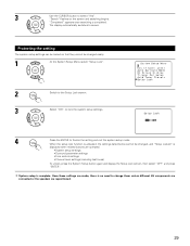
...button to screen. Protecting the setting The system setup settings can be locked so that they cannot be changed easily. 1 At the System Setup Menu select "Setup Lock". 2 Switch to the Setup Lock screen. 3 Select "ON", to lock the system setup settings. 4 Press the ENTER to change them... Surround parameter settings • Tone control settings • Channel level settings (including test tones) To unlock, press the System Setup button again and display the Setup Lock screen, then select "OFF" and press "ENTER". Once these settings are made, there is completed. "Search" flashes ...
...button to screen. Protecting the setting The system setup settings can be locked so that they cannot be changed easily. 1 At the System Setup Menu select "Setup Lock". 2 Switch to the Setup Lock screen. 3 Select "ON", to lock the system setup settings. 4 Press the ENTER to change them... Surround parameter settings • Tone control settings • Channel level settings (including test tones) To unlock, press the System Setup button again and display the Setup Lock screen, then select "OFF" and press "ENTER". Once these settings are made, there is completed. "Search" flashes ...

Owners Manual
Page 30
The changed settings are entered and the on-screen display turns off. • On-screen display signals Signals input to the AVR-2803 VIDEO signal input jack (yellow) S-video signal input jack 1 E E 2 C E 3 E C 4 C C (C: Signal E: No signal) On-screen display signal output VIDEO MONITOR OUT ...) if the monitor TV is not connected to complete the process. 1 At the System Setup Menu, press the SYSTEM SETUP button. After completing system setup This button can be pressed at any time during the system setup process to the S-video MONITOR OUT video signal output jack. 30
The changed settings are entered and the on-screen display turns off. • On-screen display signals Signals input to the AVR-2803 VIDEO signal input jack (yellow) S-video signal input jack 1 E E 2 C E 3 E C 4 C C (C: Signal E: No signal) On-screen display signal output VIDEO MONITOR OUT ...) if the monitor TV is not connected to complete the process. 1 At the System Setup Menu, press the SYSTEM SETUP button. After completing system setup This button can be pressed at any time during the system setup process to the S-video MONITOR OUT video signal output jack. 30

Owners Manual
Page 34
... component stored in the preset memory 1 Press the mode selector button for DVD changer only) DISPLAY : Display MENU : Menu RETURN : Return SETUP : Setup ENTER : Enter •, ª, 0, 1 : Cursor up, down, left and right 2. Some models cannot be operated with the remote... : Auto search (to beginning of the various components. 2 Operate the component. • For details, refer to manufacturer. Digital video disc player (DVD, DVD SETUP) system buttons POWER : Power on /standby (ON/SOURCE) 6,7 : Manual search (forward and reverse) 2 : Stop 1 : Play 8,9 : Auto search (cue) 3...
... component stored in the preset memory 1 Press the mode selector button for DVD changer only) DISPLAY : Display MENU : Menu RETURN : Return SETUP : Setup ENTER : Enter •, ª, 0, 1 : Cursor up, down, left and right 2. Some models cannot be operated with the remote... : Auto search (to beginning of the various components. 2 Operate the component. • For details, refer to manufacturer. Digital video disc player (DVD, DVD SETUP) system buttons POWER : Power on /standby (ON/SOURCE) 6,7 : Manual search (forward and reverse) 2 : Stop 1 : Play 8,9 : Auto search (cue) 3...
Owners Manual
Page 43
... of -80 to 0 to 18 dB, in the "ANALOG" or "PCM" mode. If the DIGITAL indicator does not light, check whether the digital input component setup (page 23) and connections are being input properly. 3 Select the play mode. NOTE: • The DIGITAL indicator will light when playing CD-ROMs containing data...
... of -80 to 0 to 18 dB, in the "ANALOG" or "PCM" mode. If the DIGITAL indicator does not light, check whether the digital input component setup (page 23) and connections are being input properly. 3 Select the play mode. NOTE: • The DIGITAL indicator will light when playing CD-ROMs containing data...

Owners Manual
Page 47
... control unit) 47 This operation is set to TUNER, the preset channel can be controlled only if ZONE2 vol. level is not possible in System Setup Menu. (See page 26) DEFAULT SETTING (ZONE2 VOLUME LEVEL) : - - - FUNCTION 21 Display 2 PHONO CD TUNER DVD / VDP TV / DBS MULTI VCR -1 -2 V.AUX / TAPE ZONE2 SOURCE...
... control unit) 47 This operation is set to TUNER, the preset channel can be controlled only if ZONE2 vol. level is not possible in System Setup Menu. (See page 26) DEFAULT SETTING (ZONE2 VOLUME LEVEL) : - - - FUNCTION 21 Display 2 PHONO CD TUNER DVD / VDP TV / DBS MULTI VCR -1 -2 V.AUX / TAPE ZONE2 SOURCE...


