
Owner's Manual
Page 4
... responding 36 A program crashes repeatedly 37 A program is designed for an earlier Windows operating system. . . . . 37 A solid blue screen appears 37 Other software problems 37 Memory Problems 38 Mouse Problems 38 Network Problems 39 Power Problems 40 Printer Problems 41 Scanner Problems 41 Sound and Speaker Problems 42 No sound from...
... responding 36 A program crashes repeatedly 37 A program is designed for an earlier Windows operating system. . . . . 37 A solid blue screen appears 37 Other software problems 37 Memory Problems 38 Mouse Problems 38 Network Problems 39 Power Problems 40 Printer Problems 41 Scanner Problems 41 Sound and Speaker Problems 42 No sound from...

Owner's Manual
Page 5
4 Advanced Troubleshooting Diagnostic Lights 47 Dell Diagnostics 50 When to Use the Dell Diagnostics 50 Drivers 53 What Is a Driver 53 Identifying Drivers 53 Reinstalling Drivers 54 Using Microsoft® Windows® XP System Restore 55 Creating a Restore Point 56 Restoring the Computer to an Earlier Operating State 56 Undoing the Last System Restore... View 63 Front View (Doors Open 64 Back View 65 Opening the Computer Cover 67 Inside View of Your Computer 68 System Board Components 69 Memory 70 Installing Memory 71 Removing Memory 73 Contents 5
4 Advanced Troubleshooting Diagnostic Lights 47 Dell Diagnostics 50 When to Use the Dell Diagnostics 50 Drivers 53 What Is a Driver 53 Identifying Drivers 53 Reinstalling Drivers 54 Using Microsoft® Windows® XP System Restore 55 Creating a Restore Point 56 Restoring the Computer to an Earlier Operating State 56 Undoing the Last System Restore... View 63 Front View (Doors Open 64 Back View 65 Opening the Computer Cover 67 Inside View of Your Computer 68 System Board Components 69 Memory 70 Installing Memory 71 Removing Memory 73 Contents 5

Owner's Manual
Page 11
...the topic that describes your region to view the appropriate support site. The Express Service Code is not available in all countries. Dell Support Website - The Dell Support website provides several online tools, including: • Solutions - What Are You Looking For? • Service Tag and ... technical support. support.dell.com NOTE: Select your problem. 4 Follow the instructions on your computer. •Use the Service Tag to identify your computer when you use Windows XP • Documentation for my computer • Documentation for components, such as memory, the hard drive,...
...the topic that describes your region to view the appropriate support site. The Express Service Code is not available in all countries. Dell Support Website - The Dell Support website provides several online tools, including: • Solutions - What Are You Looking For? • Service Tag and ... technical support. support.dell.com NOTE: Select your problem. 4 Follow the instructions on your computer. •Use the Service Tag to identify your computer when you use Windows XP • Documentation for my computer • Documentation for components, such as memory, the hard drive,...
Owner's Manual
Page 35
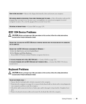
...the drive and restart your computer to restart your computer. Contact Dell (see page 123). CHECK THE KEYBOARD CABLE - • Ensure that the keyboard cable is listed, Windows recognizes the device. NOT ENOUGH MEMORY OR RESOURCES. ENSURE THAT THE CABLE FOR THE IEEE 1394 ... Device Problems CAUTION: Before you might have to restore computer resources. IF YOU HAVE PROBLEMS WITH AN IEEE 1394 DEVICE NOT PROVIDED BY DELL - Contact the IEEE 1394 device manufacturer. Straighten bent pins. • Remove keyboard extension cables and connect the keyboard directly to the ...
...the drive and restart your computer to restart your computer. Contact Dell (see page 123). CHECK THE KEYBOARD CABLE - • Ensure that the keyboard cable is listed, Windows recognizes the device. NOT ENOUGH MEMORY OR RESOURCES. ENSURE THAT THE CABLE FOR THE IEEE 1394 ... Device Problems CAUTION: Before you might have to restore computer resources. IF YOU HAVE PROBLEMS WITH AN IEEE 1394 DEVICE NOT PROVIDED BY DELL - Contact the IEEE 1394 device manufacturer. Straighten bent pins. • Remove keyboard extension cables and connect the keyboard directly to the ...
Owner's Manual
Page 38
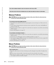
...and connect the mouse directly to ensure that your computer is successfully communicating with the memory. • Ensure that your computer, and then restart the computer. 38 Solving Problems www.dell.com | support.dell.com USE A VIRUS-SCANNING PROGRAM TO CHECK THE HARD DRIVE, FLOPPY DISKS, OR...as shown on the setup diagram for your computer is successfully communicating with the memory. • Run the Dell Diagnostics (see page 50). If necessary, install additional memory (see page 109). • Reseat the memory modules (see page 70) to see page 71). • Your computer supports...
...and connect the mouse directly to ensure that your computer is successfully communicating with the memory. • Ensure that your computer, and then restart the computer. 38 Solving Problems www.dell.com | support.dell.com USE A VIRUS-SCANNING PROGRAM TO CHECK THE HARD DRIVE, FLOPPY DISKS, OR...as shown on the setup diagram for your computer is successfully communicating with the memory. • Run the Dell Diagnostics (see page 50). If necessary, install additional memory (see page 109). • Reseat the memory modules (see page 70) to see page 71). • Your computer supports...

Owner's Manual
Page 40
...The computer is receiving electrical power, but an internal power problem might be malfunctioning or incorrectly installed. • Remove and then reinstall the memory modules (see page 70). • Remove and then reinstall any of the procedures in this section, follow the safety instructions located in ... a power strip, ensure that the power strip is securely connected to resume normal operation. IF THE POWER LIGHT IS OFF - www.dell.com | support.dell.com Power Problems CAUTION: Before you begin any cards (see page 73). • Remove and then reinstall the graphics card, if ...
...The computer is receiving electrical power, but an internal power problem might be malfunctioning or incorrectly installed. • Remove and then reinstall the memory modules (see page 70). • Remove and then reinstall any of the procedures in this section, follow the safety instructions located in ... a power strip, ensure that the power strip is securely connected to resume normal operation. IF THE POWER LIGHT IS OFF - www.dell.com | support.dell.com Power Problems CAUTION: Before you begin any cards (see page 73). • Remove and then reinstall the graphics card, if ...

Owner's Manual
Page 48
... identified a faulty module or reinstalled all modules without error. • If available, install properly working memory of the same type into your computer (see page 71). • If the problem persists, contact Dell (see page 123). • If the computer has a graphics card, remove the card (see ... ABCD Reinstall all power and data cables and restart the computer. If the computer starts normally, reinstall an additional module. www.dell.com | support.dell.com Light Pattern ABCD ABCD ABCD Problem Description Memory modules are detected, but a memory failure has occurred.
... identified a faulty module or reinstalled all modules without error. • If available, install properly working memory of the same type into your computer (see page 71). • If the problem persists, contact Dell (see page 123). • If the computer has a graphics card, remove the card (see ... ABCD Reinstall all power and data cables and restart the computer. If the computer starts normally, reinstall an additional module. www.dell.com | support.dell.com Light Pattern ABCD ABCD ABCD Problem Description Memory modules are detected, but a memory failure has occurred.
Owner's Manual
Page 49
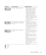
...= yellow = green = off Problem Description Suggested Resolution No memory modules are compatible with your computer (see page 71). • If the problem persists, contact Dell (see page 123). Continue until you have two or more memory modules installed, remove the modules, reinstall one module (see ...module or reinstalled all modules without error. • If available, install properly working memory of the same type into your computer (see page 70). • If the problem persists, contact Dell (see page 123). If the computer starts normally, troubleshoot the last card removed from...
...= yellow = green = off Problem Description Suggested Resolution No memory modules are compatible with your computer (see page 71). • If the problem persists, contact Dell (see page 123). Continue until you have two or more memory modules installed, remove the modules, reinstall one module (see ...module or reinstalled all modules without error. • If available, install properly working memory of the same type into your computer (see page 70). • If the problem persists, contact Dell (see page 123). If the computer starts normally, troubleshoot the last card removed from...

Owner's Manual
Page 53
... to customize the test by changing the test settings. 4 When the tests are completed, if you are running the Dell Diagnostics from system setup, memory, and various internal tests, and it displays the information in the device list in the left pane of specialized commands that... acts like a translator between the device and any device, identify whether the driver is a program that are not on your operating system. Dell ships your problem and, if necessary, update the driver. Tab Configuration Parameters Function Displays your Microsoft® Windows® operating system. A ...
... to customize the test by changing the test settings. 4 When the tests are completed, if you are running the Dell Diagnostics from system setup, memory, and various internal tests, and it displays the information in the device list in the left pane of specialized commands that... acts like a translator between the device and any device, identify whether the driver is a program that are not on your operating system. Dell ships your problem and, if necessary, update the driver. Tab Configuration Parameters Function Displays your Microsoft® Windows® operating system. A ...

Owner's Manual
Page 69
System Board Components hard-drive connector (PRI_IDE) floppy-drive connector (FLOPPY) main power connector (PWR) auxiliary power LED (AUX_PWR) memory module connectors (2, 4) memory module connectors (1, 3) processor fan (CPU FAN) processor and heatsink connector serial ATA connectors (SATA-0, SATA-1, SATA-2, SATA-3) password jumper (PASS) SCSI LED header (SCSI LED) ...
System Board Components hard-drive connector (PRI_IDE) floppy-drive connector (FLOPPY) main power connector (PWR) auxiliary power LED (AUX_PWR) memory module connectors (2, 4) memory module connectors (1, 3) processor fan (CPU FAN) processor and heatsink connector serial ATA connectors (SATA-0, SATA-1, SATA-2, SATA-3) password jumper (PASS) SCSI LED header (SCSI LED) ...

Owner's Manual
Page 70
...you install mixed pairs of PC2-3200 (DDR2 400-MHz) and PC2-4200 (DDR2 533-MHz) memory, the modules function at the slowest speed installed. • Be sure to install a single memory module in DIMM connector 1, the connector closest to the processor, before you install modules in pairs ...of the module to operate, but with a slight reduction in performance. If the DDR2 memory modules are : - See the label on the upper-right corner of matched memory size, speed, and technology. www.dell.com | support.dell.com Memory You can increase your computer, see...
...you install mixed pairs of PC2-3200 (DDR2 400-MHz) and PC2-4200 (DDR2 533-MHz) memory, the modules function at the slowest speed installed. • Be sure to install a single memory module in DIMM connector 1, the connector closest to the processor, before you install modules in pairs ...of the module to operate, but with a slight reduction in performance. If the DDR2 memory modules are : - See the label on the upper-right corner of matched memory size, speed, and technology. www.dell.com | support.dell.com Memory You can increase your computer, see...

Owner's Manual
Page 71
...) matched pair of modules in DIMM connectors 1 and 2 (white securing clips) NOTE: Memory purchased from Dell is covered under your original memory modules from the computer during a memory upgrade, keep them separate from any new modules that the system board is less than 4... GB. NOTICE: If you use four 1-GB DIMMs. Current operating systems, such as Microsoft® Windows® XP, can do not pair an original memory...
...) matched pair of modules in DIMM connectors 1 and 2 (white securing clips) NOTE: Memory purchased from Dell is covered under your original memory modules from the computer during a memory upgrade, keep them separate from any new modules that the system board is less than 4... GB. NOTICE: If you use four 1-GB DIMMs. Current operating systems, such as Microsoft® Windows® XP, can do not pair an original memory...

Owner's Manual
Page 72
www.dell.com | support.dell.com 3 Press out the securing clip at each end of the module. 5 Insert the module into the connector until the module snaps into position. memory connector closest to each end of the module with the crossbar in the connector. If you apply equal force... to processor securing clips (2) connector 4 Align the notch on the bottom of the memory module connector. notch memory module cutouts (2) crossbar NOTICE: To avoid damage to the memory module, press the module straight down into the connector while you insert the module correctly, the securing...
www.dell.com | support.dell.com 3 Press out the securing clip at each end of the module. 5 Insert the module into the connector until the module snaps into position. memory connector closest to each end of the module with the crossbar in the connector. If you apply equal force... to processor securing clips (2) connector 4 Align the notch on the bottom of the memory module connector. notch memory module cutouts (2) crossbar NOTICE: To avoid damage to the memory module, press the module straight down into the connector while you insert the module correctly, the securing...

Owner's Manual
Page 73
.... NOTICE: To prevent static damage to components inside your computer, discharge static electricity from your body before you touch any of memory (RAM) listed. Removing and Installing Parts 73 NOTICE: To prevent static damage to components inside your computer, discharge static electricity ...body before you touch any of the procedures in this section, follow the safety instructions located in the Product Information Guide. Removing Memory CAUTION: Before you begin any of your computer's electronic components. You can do so by touching an unpainted metal surface on ...
.... NOTICE: To prevent static damage to components inside your computer, discharge static electricity from your body before you touch any of memory (RAM) listed. Removing and Installing Parts 73 NOTICE: To prevent static damage to components inside your computer, discharge static electricity ...body before you touch any of the procedures in this section, follow the safety instructions located in the Product Information Guide. Removing Memory CAUTION: Before you begin any of your computer's electronic components. You can do so by touching an unpainted metal surface on ...

Owner's Manual
Page 109
...GB non-ECC 256 MB 4 GB NOTE: See "Addressing Memory With 4-GB Configurations" on page 71 to the operating system. F0000h Intel 925X Express eight 24 4-Mb Integrated network interface capable of memory available to verify the amount of 10/100/1000 communication. ...800-MHz data rate Appendix 109 Appendix Specifications Processor Processor type Level 1 (L1) cache Level 2 (L2) cache Memory Type Memory connectors Memory capacities Minimum memory Maximum memory BIOS address Computer Information Chipset DMA channels Interrupt levels BIOS chip (NVRAM) NIC System clock Intel® Pentium®...
...GB non-ECC 256 MB 4 GB NOTE: See "Addressing Memory With 4-GB Configurations" on page 71 to the operating system. F0000h Intel 925X Express eight 24 4-Mb Integrated network interface capable of memory available to verify the amount of 10/100/1000 communication. ...800-MHz data rate Appendix 109 Appendix Specifications Processor Processor type Level 1 (L1) cache Level 2 (L2) cache Memory Type Memory connectors Memory capacities Minimum memory Maximum memory BIOS address Computer Information Chipset DMA channels Interrupt levels BIOS chip (NVRAM) NIC System clock Intel® Pentium®...
Owner's Manual
Page 110
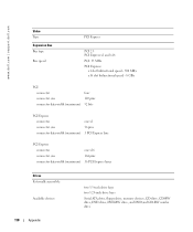
www.dell.com | support.dell.com Video Type Expansion Bus Bus type Bus speed PCI Express PCI 2.3 PCI Express x1 and x16 PCI: 33 MHz PCI Express: x1 slot bidirectional ... width (maximum) 16 PCI Express lanes Drives Externally accessible: Available devices two 3.5-inch drive bays two 5.25-inch drive bays Serial ATA drive, floppy drive, memory devices, CD drive, CD-RW drive, DVD drive, DVD-RW drive, and DVD and CD-RW combo drive 110 Appendix
www.dell.com | support.dell.com Video Type Expansion Bus Bus type Bus speed PCI Express PCI 2.3 PCI Express x1 and x16 PCI: 33 MHz PCI Express: x1 slot bidirectional ... width (maximum) 16 PCI Express lanes Drives Externally accessible: Available devices two 3.5-inch drive bays two 5.25-inch drive bays Serial ATA drive, floppy drive, memory devices, CD drive, CD-RW drive, DVD drive, DVD-RW drive, and DVD and CD-RW combo drive 110 Appendix

Owner's Manual
Page 113
... that you add, change, or remove any hardware in velocity of 20 inches/sec (50.8 cm/sec) 27-G faired square wave with a velocity change of memory or set or change the settings for future reference. Certain changes can make your computer • To set the type of hard drive installed Before...
... that you add, change, or remove any hardware in velocity of 20 inches/sec (50.8 cm/sec) 27-G faired square wave with a velocity change of memory or set or change the settings for future reference. Certain changes can make your computer • To set the type of hard drive installed Before...
Owner's Manual
Page 115
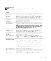
...it becomes the first device in the boot sequence list. Enables or disables the onboard PS/2-compatible mouse controller. Indicates amount of installed memory, memory speed, channel mode (dual or single), and type of devices specified in this list. The computer attempts to RAID Autodetect/AHCI,...-Threading and lists the processor bus speed, processor ID, clock speed, and L2 cache. Appendix 115 System System Info CPU Info Memory Info Date/Time Boot Sequence Drives Diskette Drive Drives 0 through 5 Drive Controller Onboard Devices NIC Controller Audio Controller USB Mouse Port Lists...
...it becomes the first device in the boot sequence list. Enables or disables the onboard PS/2-compatible mouse controller. Indicates amount of installed memory, memory speed, channel mode (dual or single), and type of devices specified in this list. The computer attempts to RAID Autodetect/AHCI,...-Threading and lists the processor bus speed, processor ID, clock speed, and L2 cache. Appendix 115 System System Info CPU Info Memory Info Date/Time Boot Sequence Drives Diskette Drive Drives 0 through 5 Drive Controller Onboard Devices NIC Controller Audio Controller USB Mouse Port Lists...

Owner's Manual
Page 117
... power is enabled, the computer can be powered up from Suspend. This feature does not work if you turn off for most components, however, system memory remains active. After downloading a new version of the BIOS, use this option activates the cursor-control functions labeled on the bottom of keys on . Auto...
... power is enabled, the computer can be powered up from Suspend. This feature does not work if you turn off for most components, however, system memory remains active. After downloading a new version of the BIOS, use this option activates the cursor-control functions labeled on the bottom of keys on . Auto...

Owner's Manual
Page 118
... this feature, for example, to tell the computer to boot from the CD drive so that your computer to a USB device such as a floppy drive, memory key, or CD-RW drive. Changing Boot Sequence for devices. Each device has a number next to the boot menu. The computer attempts to boot from... Windows desktop. NOTE: If you are booting to a USB floppy drive, you to change the boot sequence for the Current Boot You can run the Dell Diagnostics on the drive, the computer generates an error message. • CD Drive - The computer attempts to a USB connector (see page 69). 2 Turn on the...
... this feature, for example, to tell the computer to boot from the CD drive so that your computer to a USB device such as a floppy drive, memory key, or CD-RW drive. Changing Boot Sequence for devices. Each device has a number next to the boot menu. The computer attempts to boot from... Windows desktop. NOTE: If you are booting to a USB floppy drive, you to change the boot sequence for the Current Boot You can run the Dell Diagnostics on the drive, the computer generates an error message. • CD Drive - The computer attempts to a USB connector (see page 69). 2 Turn on the...


