
Owner's Manual
Page 2
... Model DCDO October 2006 P/N HY898 Rev. Abbreviations and Acronyms For a complete list of Intel Corporation; Reproduction in this text: Dell, the DELL logo, Dell XPS, Inspiron, Dell Precision, Dimension, OptiPlex, Latitude, PowerEdge, PowerVault, PowerApp, and Dell OpenManage are not applicable. Trademarks used in this document to refer to either potential damage to hardware or loss of...
... Model DCDO October 2006 P/N HY898 Rev. Abbreviations and Acronyms For a complete list of Intel Corporation; Reproduction in this text: Dell, the DELL logo, Dell XPS, Inspiron, Dell Precision, Dimension, OptiPlex, Latitude, PowerEdge, PowerVault, PowerApp, and Dell OpenManage are not applicable. Trademarks used in this document to refer to either potential damage to hardware or loss of...

Owner's Manual
Page 3
book.book Page 3 Friday, October 27, 2006 4:02 PM Contents Finding Information 9 1 Setting Up and Using Your Computer 13 Front and Back View of the Computer 13 Front View 13 Front I/O Connectors 15 Back View 16 Back I/O Connectors 17 Attaching the Computer Stand 18 Connecting Monitors 20 Connecting a Monitor (Without an Adapter 20 Connecting a Monitor (With an Adapter 21 Connecting a Monitor in a Dual Graphics Card Configuration 22 Connecting Two or More Monitors 23 Connecting a TV (S-Video 24 Changing the Display Settings to Support Two or More Monitors . . . . . 25 About ...
book.book Page 3 Friday, October 27, 2006 4:02 PM Contents Finding Information 9 1 Setting Up and Using Your Computer 13 Front and Back View of the Computer 13 Front View 13 Front I/O Connectors 15 Back View 16 Back I/O Connectors 17 Attaching the Computer Stand 18 Connecting Monitors 20 Connecting a Monitor (Without an Adapter 20 Connecting a Monitor (With an Adapter 21 Connecting a Monitor in a Dual Graphics Card Configuration 22 Connecting Two or More Monitors 23 Connecting a TV (S-Video 24 Changing the Display Settings to Support Two or More Monitors . . . . . 25 About ...
Owner's Manual
Page 4
book.book Page 4 Friday, October 27, 2006 4:02 PM Network Setup Wizard 38 Transferring Information to a New Computer 38 Power Management 39 Overview 39 Standby Mode 39 Hibernate Mode 40 Power Options Properties 40 2 Optimizing Performance 43 Understanding PCI Express Cards 43 Understanding Dual Graphics Technology 43 Understanding CPU Over-Clocking 43 3 Solving Problems 45 Troubleshooting Tips 45 Battery Problems 45 Drive Problems 45 CD and DVD drive problems 46 Hard drive problems 47 E-Mail, Modem, and Internet Problems 47 Error Messages 48 IEEE 1394 Device Problems 49 ...
book.book Page 4 Friday, October 27, 2006 4:02 PM Network Setup Wizard 38 Transferring Information to a New Computer 38 Power Management 39 Overview 39 Standby Mode 39 Hibernate Mode 40 Power Options Properties 40 2 Optimizing Performance 43 Understanding PCI Express Cards 43 Understanding Dual Graphics Technology 43 Understanding CPU Over-Clocking 43 3 Solving Problems 45 Troubleshooting Tips 45 Battery Problems 45 Drive Problems 45 CD and DVD drive problems 46 Hard drive problems 47 E-Mail, Modem, and Internet Problems 47 Error Messages 48 IEEE 1394 Device Problems 49 ...

Owner's Manual
Page 5
... blank 58 The screen is difficult to read 59 3-D image quality is poor 59 4 Advanced Troubleshooting 61 Diagnostic Lights 61 Dell Diagnostics 64 When to Use the Dell Diagnostics 64 Drivers 67 What Is a Driver 67 Identifying Drivers 67 Reinstalling Drivers 67 Using Microsoft® Windows®...; XP System Restore 69 Creating a Restore Point 69 Restoring the Computer to an Earlier Operating State 70 Undoing the Last System ...
... blank 58 The screen is difficult to read 59 3-D image quality is poor 59 4 Advanced Troubleshooting 61 Diagnostic Lights 61 Dell Diagnostics 64 When to Use the Dell Diagnostics 64 Drivers 67 What Is a Driver 67 Identifying Drivers 67 Reinstalling Drivers 67 Using Microsoft® Windows®...; XP System Restore 69 Creating a Restore Point 69 Restoring the Computer to an Earlier Operating State 70 Undoing the Last System ...

Owner's Manual
Page 6
book.book Page 6 Friday, October 27, 2006 4:02 PM 5 Removing and Installing Parts 75 Before You Begin 75 Recommended Tools 75 Preparing to Work Inside Your Computer 75 Removing the Computer Cover 76 Inside View of Your Computer 78 System Board Components 79 Memory 80 DDR2 Memory Overview 80 Addressing Memory Configurations 82 Installing Memory 82 Removing Memory 84 Cards 84 Removing PCI and PCI Express Cards 85 Installing PCI and PCI Express Cards 87 Removing a PCI Express Graphics Card from a Dual Configuration . . . . 91 Installing a PCI Express Graphics Card in a Dual ...
book.book Page 6 Friday, October 27, 2006 4:02 PM 5 Removing and Installing Parts 75 Before You Begin 75 Recommended Tools 75 Preparing to Work Inside Your Computer 75 Removing the Computer Cover 76 Inside View of Your Computer 78 System Board Components 79 Memory 80 DDR2 Memory Overview 80 Addressing Memory Configurations 82 Installing Memory 82 Removing Memory 84 Cards 84 Removing PCI and PCI Express Cards 85 Installing PCI and PCI Express Cards 87 Removing a PCI Express Graphics Card from a Dual Configuration . . . . 91 Installing a PCI Express Graphics Card in a Dual ...
Owner's Manual
Page 7
Only 145 Definition of "Dell-Installed" Software and Peripherals 145 Definition of "Third-Party" Software and Peripherals 145 Contents 7 book.book Page 7 Friday, October 27, 2006 4:02 PM CD/DVD ... Forgotten Passwords 142 Clearing CMOS Settings 143 Cleaning Your Computer 143 Computer, Keyboard, and Monitor 143 Mouse 144 Floppy Drive 144 CDs and DVDs 144 Dell Hardware Warranty Support Policy (U.S.
Only 145 Definition of "Dell-Installed" Software and Peripherals 145 Definition of "Third-Party" Software and Peripherals 145 Contents 7 book.book Page 7 Friday, October 27, 2006 4:02 PM CD/DVD ... Forgotten Passwords 142 Clearing CMOS Settings 143 Cleaning Your Computer 143 Computer, Keyboard, and Monitor 143 Mouse 144 Floppy Drive 144 CDs and DVDs 144 Dell Hardware Warranty Support Policy (U.S.

Owner's Manual
Page 8
book.book Page 8 Friday, October 27, 2006 4:02 PM FCC Notices (U.S. Only 145 Class A 146 Class B 146 FCC Identification Information 147 Contacting Dell 147 Glossary 169 Index 179 8 Contents
book.book Page 8 Friday, October 27, 2006 4:02 PM FCC Notices (U.S. Only 145 Class A 146 Class B 146 FCC Identification Information 147 Contacting Dell 147 Glossary 169 Index 179 8 Contents

Owner's Manual
Page 9
... updates about technical changes to reinstall drivers (see "Reinstalling Drivers" on page 67), access your documentation or run the Dell Diagnostics (see "Dell Diagnostics" on your computer. Dell™ Product Information Guide Finding Information 9 book.book Page 9 Friday, October 27, 2006 4:02 PM Finding Information NOTE...Some features or media may be optional and may not ship with your computer. Some features or media may not be found at support.dell.com. You can be available in certain countries. What Are You Looking For? • A diagnostic program for my computer •...
... updates about technical changes to reinstall drivers (see "Reinstalling Drivers" on page 67), access your documentation or run the Dell Diagnostics (see "Dell Diagnostics" on your computer. Dell™ Product Information Guide Finding Information 9 book.book Page 9 Friday, October 27, 2006 4:02 PM Finding Information NOTE...Some features or media may be optional and may not ship with your computer. Some features or media may not be found at support.dell.com. You can be available in certain countries. What Are You Looking For? • A diagnostic program for my computer •...

Owner's Manual
Page 10
book.book Page 10 Friday, October 27, 2006 4:02 PM What Are You Looking For? • How to set up my computer Find It Here Setup Diagram • Service Tag and Express Service Code • Microsoft® Windows® Product Key Label Service Tag and Microsoft Windows Product Key These labels are located on your computer. • Use the Service Tag to identify your computer when you use support.dell.com or contact support. • Enter the Express Service Code to direct your call when contacting support. 10 Finding Information
book.book Page 10 Friday, October 27, 2006 4:02 PM What Are You Looking For? • How to set up my computer Find It Here Setup Diagram • Service Tag and Express Service Code • Microsoft® Windows® Product Key Label Service Tag and Microsoft Windows Product Key These labels are located on your computer. • Use the Service Tag to identify your computer when you use support.dell.com or contact support. • Enter the Express Service Code to direct your call when contacting support. 10 Finding Information

Owner's Manual
Page 11
Troubleshooting hints and tips, articles from technicians, online courses, and frequently asked questions Dell Support Website - depending on your selections. • How to use Windows XP • How to work with programs and files • How to view the appropriate support site. • Community - Contact information, service call status, support history, ...
Troubleshooting hints and tips, articles from technicians, online courses, and frequently asked questions Dell Support Website - depending on your selections. • How to use Windows XP • How to work with programs and files • How to view the appropriate support site. • Community - Contact information, service call status, support history, ...

Owner's Manual
Page 12
... Operating System CD varies according to the operating system you reinstall the operating system, use the Operating System CD (see "Reinstalling Microsoft® Windows® XP" on your computer. After you ordered. 12 Finding Information To reinstall your operating system, use the Drivers and Utilities CD to reinstall drivers for the...
... Operating System CD varies according to the operating system you reinstall the operating system, use the Operating System CD (see "Reinstalling Microsoft® Windows® XP" on your computer. After you ordered. 12 Finding Information To reinstall your operating system, use the Drivers and Utilities CD to reinstall drivers for the...

Owner's Manual
Page 13
Can hold an optional Media Card Reader or floppy drive. Setting Up and Using Your Computer 13 book.book Page 13 Friday, October 27, 2006 4:02 PM Setting Up and Using Your Computer Front and Back View of the Computer Front View 7 6 8 5 4 3 2 9 1 10 11 12 1 front I/O connectors 2 3.5-inch drive bays (2) Plug USB and other devices into the appropriate connectors (see "Front I/O Connectors" on page 15).
Can hold an optional Media Card Reader or floppy drive. Setting Up and Using Your Computer 13 book.book Page 13 Friday, October 27, 2006 4:02 PM Setting Up and Using Your Computer Front and Back View of the Computer Front View 7 6 8 5 4 3 2 9 1 10 11 12 1 front I/O connectors 2 3.5-inch drive bays (2) Plug USB and other devices into the appropriate connectors (see "Front I/O Connectors" on page 15).
Owner's Manual
Page 14
NOTE: The hard-drive carrier is ejected. 9 front panel LEDs (4) Multi-colored lights provide illumination for the front of the computer. NOTE: The color of the computer. NOTICE: To avoid losing data, do not use in system setup (see "System Setup" on the computer. NOTE: The power button can be installed at all times to the system. The floppy-drive/Media Card Reader and hard-drive carriers are not interchangeable. 7 front panel LEDs (4) Multi-colored lights provide illumination for the front of the front panel LEDs can be adjusted in the 5.25-inch drive bays. The self-tending...
NOTE: The hard-drive carrier is ejected. 9 front panel LEDs (4) Multi-colored lights provide illumination for the front of the computer. NOTE: The color of the computer. NOTICE: To avoid losing data, do not use in system setup (see "System Setup" on the computer. NOTE: The power button can be installed at all times to the system. The floppy-drive/Media Card Reader and hard-drive carriers are not interchangeable. 7 front panel LEDs (4) Multi-colored lights provide illumination for the front of the front panel LEDs can be adjusted in the 5.25-inch drive bays. The self-tending...
Owner's Manual
Page 15
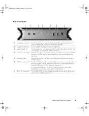
Setting Up and Using Your Computer 15 It is recommended that typically remain connected, such as printers and keyboards. 7 IEEE 1394a connector Use the IEEE 1394a connector for high-speed data devices such as digital video cameras and external storage devices. For more information on bootable USB devices see "Diagnostic Lights" on page 61). 4 hard-drive activity light The hard drive light is on when a good connection exists between a network and the computer. 6 USB 2.0 connectors (2) Use the front USB connectors for devices that you use the back USB connectors for devices that ...
Setting Up and Using Your Computer 15 It is recommended that typically remain connected, such as printers and keyboards. 7 IEEE 1394a connector Use the IEEE 1394a connector for high-speed data devices such as digital video cameras and external storage devices. For more information on bootable USB devices see "Diagnostic Lights" on page 61). 4 hard-drive activity light The hard drive light is on when a good connection exists between a network and the computer. 6 USB 2.0 connectors (2) Use the front USB connectors for devices that you use the back USB connectors for devices that ...

Owner's Manual
Page 16
Multi-colored lights provide illumination for any installed PCI or PCI Express cards. NOTE: The color of the back panel LEDs can be adjusted in system setup (see "Back I /O connectors 4 card slots Insert the power cable. Plug serial, USB, and other devices into the appropriate connectors (see "System Setup" on the back of this connector may differ from what is pictured. Access connectors for the I/O panel on page 134). NOTE: Some connector slots support full-length cards. 16 Setting Up and Using Your Computer book.book Page 16 Friday, October 27, 2006 4:02 PM Back View 1 2 3 4 ...
Multi-colored lights provide illumination for any installed PCI or PCI Express cards. NOTE: The color of the back panel LEDs can be adjusted in system setup (see "Back I /O connectors 4 card slots Insert the power cable. Plug serial, USB, and other devices into the appropriate connectors (see "System Setup" on the back of this connector may differ from what is pictured. Access connectors for the I/O panel on page 134). NOTE: Some connector slots support full-length cards. 16 Setting Up and Using Your Computer book.book Page 16 Friday, October 27, 2006 4:02 PM Back View 1 2 3 4 ...

Owner's Manual
Page 17
If you have a USB mouse, plug it into the network adapter connector. A high volume of the computer when setting up multiple network connections (such as a separate intra- Plug a standard PS/2 mouse into the purple keyboard connector. The computer is transmitting or receiving network data. On computers with an additional network connector card, use the connectors on the card and on the back of network traffic may make this light appear to be in a steady "on your computer to attach your computer. Plug a standard PS/2 keyboard into the green mouse connector. Setting ...
If you have a USB mouse, plug it into the network adapter connector. A high volume of the computer when setting up multiple network connections (such as a separate intra- Plug a standard PS/2 mouse into the purple keyboard connector. The computer is transmitting or receiving network data. On computers with an additional network connector card, use the connectors on the card and on the back of network traffic may make this light appear to be in a steady "on your computer to attach your computer. Plug a standard PS/2 keyboard into the green mouse connector. Setting ...

Owner's Manual
Page 18
On computers with a sound card, use the connector on the card. On computers with a sound card, use the front USB connectors for devices that you connect occasionally, such as flash memory keys, cameras, or bootable USB devices. Use the (blue) line-in the Product Information Guide. Attaching the Computer Stand CAUTION: Before you use the connector on the card. Seek assistance before attempting to lift, move, or tilt the computer and always lift correctly to attach a single subwoofer. Use the (orange) subwoofer connector to avoid injury; On computers with a sound card, ...
On computers with a sound card, use the connector on the card. On computers with a sound card, use the front USB connectors for devices that you connect occasionally, such as flash memory keys, cameras, or bootable USB devices. Use the (blue) line-in the Product Information Guide. Attaching the Computer Stand CAUTION: Before you use the connector on the card. Seek assistance before attempting to lift, move, or tilt the computer and always lift correctly to attach a single subwoofer. Use the (orange) subwoofer connector to avoid injury; On computers with a sound card, ...

Owner's Manual
Page 19
Failure to install the stand could result in the computer tipping over, potentially resulting in bodily injury or damage to the computer. 1 Follow the procedures in the slots. 4 Ensure that is installed on the base of the computer. 5 Insert the captive screw into the open position. NOTE: If the thumb screw is not already installed in the stand, it has been packaged separately. 3 Insert the six alignment tabs into the corresponding slots on the base of the computer, then slide the stand forward until all times to the base of the computer. 1 2 3 4 1 captive screw 4 slots (6) 2 ...
Failure to install the stand could result in the computer tipping over, potentially resulting in bodily injury or damage to the computer. 1 Follow the procedures in the slots. 4 Ensure that is installed on the base of the computer. 5 Insert the captive screw into the open position. NOTE: If the thumb screw is not already installed in the stand, it has been packaged separately. 3 Insert the six alignment tabs into the corresponding slots on the base of the computer, then slide the stand forward until all times to the base of the computer. 1 2 3 4 1 captive screw 4 slots (6) 2 ...

Owner's Manual
Page 20
If you perform any of the procedures in this section, follow the safety instructions in the Product Information Guide. The computer performs a shutdown of the operating system, and then turns off and not in a power management mode. NOTE: Ensure that the computer is off . NOTE: If your monitor has a VGA connector and your video card may have a VGA port, follow the instructions in "Connecting a Monitor (With an Adapter)" on the options selected when you purchased your computer, your computer does not have two DVI ports, or one DVI and one VGA port. 1 2 3 1 DVI (white) connector...
If you perform any of the procedures in this section, follow the safety instructions in the Product Information Guide. The computer performs a shutdown of the operating system, and then turns off and not in a power management mode. NOTE: Ensure that the computer is off . NOTE: If your monitor has a VGA connector and your video card may have a VGA port, follow the instructions in "Connecting a Monitor (With an Adapter)" on the options selected when you purchased your computer, your computer does not have two DVI ports, or one DVI and one VGA port. 1 2 3 1 DVI (white) connector...

Owner's Manual
Page 21
b In the Turn off computer window, click Turn off . The computer performs a shutdown of the procedures in this section, follow the safety instructions in a power management mode. Setting Up and Using Your Computer 21 If you perform any of the operating system, and then turns off . NOTE: In order to connect a monitor with a VGA connector to the DVI port on the back of the computer: To connect a monitor with a DVI connector, use the (white) DVI port on your computer, a DVI-toVGA adapter is off and not in the Product Information Guide. NOTE: When connecting a single ...
b In the Turn off computer window, click Turn off . The computer performs a shutdown of the procedures in this section, follow the safety instructions in a power management mode. Setting Up and Using Your Computer 21 If you perform any of the operating system, and then turns off . NOTE: In order to connect a monitor with a VGA connector to the DVI port on the back of the computer: To connect a monitor with a DVI connector, use the (white) DVI port on your computer, a DVI-toVGA adapter is off and not in the Product Information Guide. NOTE: When connecting a single ...
