
Service Manual
Page 3
Contents 1 Before You Begin 9 Recommended Tools 9 Turning Off Your Computer 9 Before Working Inside Your Computer 10 2 Battery 13 Removing the Battery 13 Replacing the Battery 14 3 Module Cover 15 Removing the Module Cover 15 Replacing the Module Cover 16 4 Memory Module(s 17 Removing the Memory Module(s 17 Replacing the Memory Module(s 18 5 Wireless Mini-Card(s 21 Removing the Mini-Card(s 21 Contents 3
Contents 1 Before You Begin 9 Recommended Tools 9 Turning Off Your Computer 9 Before Working Inside Your Computer 10 2 Battery 13 Removing the Battery 13 Replacing the Battery 14 3 Module Cover 15 Removing the Module Cover 15 Replacing the Module Cover 16 4 Memory Module(s 17 Removing the Memory Module(s 17 Replacing the Memory Module(s 18 5 Wireless Mini-Card(s 21 Removing the Mini-Card(s 21 Contents 3

Service Manual
Page 5
... 43 Removing the Keyboard 43 Replacing the Keyboard 45 12 Display 49 Display Assembly 49 Removing the Display Assembly 49 Replacing the Display Assembly 52 Display Bezel 53 Removing the Display Bezel 53 Replacing the Display Bezel 54 Display Panel 54 Removing the Display Panel 54 Replacing the Display Panel 57 Display Cable 57 Removing the Display Cable 57 Replacing the Display Cable 58 Display-Panel Brackets 59 Removing the Display-Panel Brackets 59 Replacing the Display-Panel Brackets 60 13 Camera Module 61 Removing the Camera Module 61 Replacing the Camera Module 62...
... 43 Removing the Keyboard 43 Replacing the Keyboard 45 12 Display 49 Display Assembly 49 Removing the Display Assembly 49 Replacing the Display Assembly 52 Display Bezel 53 Removing the Display Bezel 53 Replacing the Display Bezel 54 Display Panel 54 Removing the Display Panel 54 Replacing the Display Panel 57 Display Cable 57 Removing the Display Cable 57 Replacing the Display Cable 58 Display-Panel Brackets 59 Removing the Display-Panel Brackets 59 Replacing the Display-Panel Brackets 60 13 Camera Module 61 Removing the Camera Module 61 Replacing the Camera Module 62...

Service Manual
Page 7
19 TV Tuner Connector 87 Removing the TV Tuner Connector 87 Replacing the TV Tuner Connector 88 20 Heat Sink 91 Removing the Heat Sink 91 Replacing the Heat Sink 92 21 Processor Module 95 Removing the Processor Module 95 Replacing the Processor Module 97 22 System Board 99 Removing the System Board 99 Replacing the System Board 101 Entering the Service Tag in the BIOS 102 23 Speakers 105 Removing the Speakers 105 Replacing the Speakers 106 24 Flashing the BIOS 109 Contents 7
19 TV Tuner Connector 87 Removing the TV Tuner Connector 87 Replacing the TV Tuner Connector 88 20 Heat Sink 91 Removing the Heat Sink 91 Replacing the Heat Sink 92 21 Processor Module 95 Removing the Processor Module 95 Replacing the Processor Module 97 22 System Board 99 Removing the System Board 99 Replacing the System Board 101 Entering the Service Tag in the BIOS 102 23 Speakers 105 Removing the Speakers 105 Replacing the Speakers 106 24 Flashing the BIOS 109 Contents 7

Service Manual
Page 17
... computer has two user-accessible SODIMM connectors. NOTE: Memory modules purchased from Dell are covered under your fingertips to carefully spread apart the securing clips on your computer. CAUTION: To avoid electrostatic discharge, ground yourself by using a wrist grounding strap or by installing memory modules on your computer). Removing the Memory Module(s) 1 Follow the instructions in the Setup Guide that is not authorized by Dell™ is not...
... computer has two user-accessible SODIMM connectors. NOTE: Memory modules purchased from Dell are covered under your fingertips to carefully spread apart the securing clips on your computer. CAUTION: To avoid electrostatic discharge, ground yourself by using a wrist grounding strap or by installing memory modules on your computer). Removing the Memory Module(s) 1 Follow the instructions in the Setup Guide that is not authorized by Dell™ is not...

Service Manual
Page 23
...card and on page 9. 2 Remove the new Mini-Card from its packaging. Replacing the Mini-Card(s) 1 Follow the instructions in the safety information that shipped with your computer. Wireless Mini-Card(s) 23 For more information, see "Protecting Against Electrostatic Discharge" in "Before You Begin" on the system board, and realign the card. CAUTION: Use... firm and even pressure to ensure correct insertion. If you may damage the connector. CAUTION: The connectors are keyed to slide the card into place. CAUTION: When the Mini-Card is ...
...card and on page 9. 2 Remove the new Mini-Card from its packaging. Replacing the Mini-Card(s) 1 Follow the instructions in the safety information that shipped with your computer. Wireless Mini-Card(s) 23 For more information, see "Protecting Against Electrostatic Discharge" in "Before You Begin" on the system board, and realign the card. CAUTION: Use... firm and even pressure to ensure correct insertion. If you may damage the connector. CAUTION: The connectors are keyed to slide the card into place. CAUTION: When the Mini-Card is ...
Service Manual
Page 24
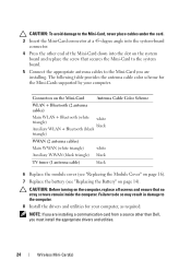
.... 8 Install the drivers and utilities for the Mini-Cards supported by your computer, as required. Connectors on the Mini-Card Antenna Cable Color Scheme WLAN + Bluetooth (2 antenna cables) Main WLAN + Bluetooth (white triangle) white Auxiliary WLAN + Bluetooth (black black triangle) WWAN (2 antenna cables) Main WWAN (white triangle) white Auxiliary WWAN (black triangle) black TV tuner (1 antenna cable) black 6 Replace the module cover (see "Replacing the Module Cover" on page 16). 7 Replace the battery (see "Replacing the Battery" on...
.... 8 Install the drivers and utilities for the Mini-Cards supported by your computer, as required. Connectors on the Mini-Card Antenna Cable Color Scheme WLAN + Bluetooth (2 antenna cables) Main WLAN + Bluetooth (white triangle) white Auxiliary WLAN + Bluetooth (black black triangle) WWAN (2 antenna cables) Main WWAN (white triangle) white Auxiliary WWAN (black triangle) black TV tuner (1 antenna cable) black 6 Replace the module cover (see "Replacing the Module Cover" on page 16). 7 Replace the battery (see "Replacing the Battery" on...

Service Manual
Page 26
... Replacing the Optical Drive 1 Follow the instructions in "Before You Begin" on page 9. 2 Remove the new optical drive from its packaging. 3 Slide the optical drive into the optical-drive bay until it is fully seated. 4 Replace the screw that secures the optical drive to the base cover. 5 Replace the memory module(s) (see "Replacing the Memory Module(s)" on page 18). 6 Replace the module cover (see "Replacing the Module Cover" on page 16). 7 Replace the battery (see "Replacing...
... Replacing the Optical Drive 1 Follow the instructions in "Before You Begin" on page 9. 2 Remove the new optical drive from its packaging. 3 Slide the optical drive into the optical-drive bay until it is fully seated. 4 Replace the screw that secures the optical drive to the base cover. 5 Replace the memory module(s) (see "Replacing the Memory Module(s)" on page 18). 6 Replace the module cover (see "Replacing the Module Cover" on page 16). 7 Replace the battery (see "Replacing...
Service Manual
Page 53
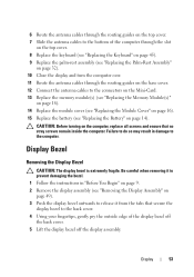
...-Card. 13 Replace the memory module(s) (see "Replacing the Memory Module(s)" on page 18). 14 Replace the module cover (see "Replacing the Module Cover" on page 16). 15 Replace the battery (see "Replacing the Palm-Rest Assembly" on page 32). 10 Close the display and turn the computer over. 11 Route the antenna cables through the slot on the top cover. 8 Replace the keyboard (see "Replacing the Keyboard" on page 45). 9 Replace the palm-rest assembly (see "Replacing...
...-Card. 13 Replace the memory module(s) (see "Replacing the Memory Module(s)" on page 18). 14 Replace the module cover (see "Replacing the Module Cover" on page 16). 15 Replace the battery (see "Replacing the Palm-Rest Assembly" on page 32). 10 Close the display and turn the computer over. 11 Route the antenna cables through the slot on the top cover. 8 Replace the keyboard (see "Replacing the Keyboard" on page 45). 9 Replace the palm-rest assembly (see "Replacing...

Service Manual
Page 65
... instructions in "Before You Begin" on page 9. 2 Press and eject any installed cards from the Media Card Reader. 3 Remove the battery (see "Removing the Battery" on page 13). 4 Remove the module cover (see "Removing the Module Cover" on page 15). 5 Remove the memory module(s) (see "Removing the Memory Module(s)" on page 17). 6 Remove the palm-rest assembly (see "Removing the Palm-Rest Assembly" on page 29). 7 Remove the keyboard (see "Removing the Keyboard" on page 43). 8 Remove the display assembly (see "Removing...
... instructions in "Before You Begin" on page 9. 2 Press and eject any installed cards from the Media Card Reader. 3 Remove the battery (see "Removing the Battery" on page 13). 4 Remove the module cover (see "Removing the Module Cover" on page 15). 5 Remove the memory module(s) (see "Removing the Memory Module(s)" on page 17). 6 Remove the palm-rest assembly (see "Removing the Palm-Rest Assembly" on page 29). 7 Remove the keyboard (see "Removing the Keyboard" on page 43). 8 Remove the display assembly (see "Removing...

Service Manual
Page 69
... display assembly (see "Replacing the Display Assembly" on page 52). 13 Replace the keyboard (see "Replacing the Keyboard" on page 45). 14 Replace the palm-rest assembly (see "Replacing the Palm-Rest Assembly" on page 32). 15 Replace the memory module(s) (see "Replacing the Memory Module(s)" on page 18). 16 Replace the module cover (see "Replacing the Module Cover" on page 16). 17 Replace any blank or card you removed from the Media Card Reader. 18 Replace the battery (see "Replacing...
... display assembly (see "Replacing the Display Assembly" on page 52). 13 Replace the keyboard (see "Replacing the Keyboard" on page 45). 14 Replace the palm-rest assembly (see "Replacing the Palm-Rest Assembly" on page 32). 15 Replace the memory module(s) (see "Replacing the Memory Module(s)" on page 18). 16 Replace the module cover (see "Replacing the Module Cover" on page 16). 17 Replace any blank or card you removed from the Media Card Reader. 18 Replace the battery (see "Replacing...
Service Manual
Page 102
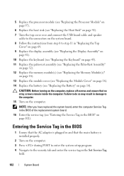
... adapter is installed properly. 2 Turn on the computer. 3 Press during POST to enter the system setup program. 4 Navigate to the security tab and enter the service tag in the BIOS" on page 102). 5 Replace the processor module (see "Replacing the Processor Module" on page 97). 6 Replace the heat sink (see "Replacing the Heat Sink" on page 92). 7 Turn the top cover over and connect the USB board cable and speaker cable...
... adapter is installed properly. 2 Turn on the computer. 3 Press during POST to enter the system setup program. 4 Navigate to the security tab and enter the service tag in the BIOS" on page 102). 5 Replace the processor module (see "Replacing the Processor Module" on page 97). 6 Replace the heat sink (see "Replacing the Heat Sink" on page 92). 7 Turn the top cover over and connect the USB board cable and speaker cable...

XPS 15 L502X Setup Guide
Page 5
... Windows 11 Create System Recovery Media (Recommended 12 Install the SIM Card (Optional 14 Enable or Disable Wireless (Optional 16 Set Up Wireless Display (Optional 18 Set Up the TV Tuner (Optional 19 Set Up 3D TV (Optional 20 Connect to the Internet (Optional 22 Using Your XPS Laptop 24 Right View Features 24 Left View Features 28 Front View Features 29 Back View Features 30 Computer Base and Keyboard Features 32 Status Lights and Indicators 36 Disabling Battery Charging 37 Touch Pad...
... Windows 11 Create System Recovery Media (Recommended 12 Install the SIM Card (Optional 14 Enable or Disable Wireless (Optional 16 Set Up Wireless Display (Optional 18 Set Up the TV Tuner (Optional 19 Set Up 3D TV (Optional 20 Connect to the Internet (Optional 22 Using Your XPS Laptop 24 Right View Features 24 Left View Features 28 Front View Features 29 Back View Features 30 Computer Base and Keyboard Features 32 Status Lights and Indicators 36 Disabling Battery Charging 37 Touch Pad...
XPS 15 L502X Setup Guide
Page 6
... Removing and Replacing the Battery 50 Software Features 52 Dell DataSafe Online Backup 53 Dell Stage 54 NVIDIA Optimus Technology (Optional 56 NVIDIA 3DTV Play 57 Free Fall Sensor 61 Solving Problems 62 Beep Codes 62 Touch Screen Problems 63 Network Problems 64 Power Problems 65 Memory Problems 66 Lockups and Software Problems 67 Using Support Tools 69 Dell Support Center 69 My Dell Downloads 70 Hardware Troubleshooter 71 Dell Diagnostics 71 Restoring Your Operating System 76 System Restore 77 Dell DataSafe Local Backup 78 System Recovery Media...
... Removing and Replacing the Battery 50 Software Features 52 Dell DataSafe Online Backup 53 Dell Stage 54 NVIDIA Optimus Technology (Optional 56 NVIDIA 3DTV Play 57 Free Fall Sensor 61 Solving Problems 62 Beep Codes 62 Touch Screen Problems 63 Network Problems 64 Power Problems 65 Memory Problems 66 Lockups and Software Problems 67 Using Support Tools 69 Dell Support Center 69 My Dell Downloads 70 Hardware Troubleshooter 71 Dell Diagnostics 71 Restoring Your Operating System 76 System Restore 77 Dell DataSafe Local Backup 78 System Recovery Media...
XPS 15 L502X Setup Guide
Page 21
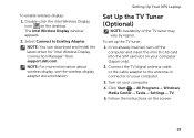
... mini B-CAS card into the SIM card slot on the desktop. NOTE: You can download and install the latest driver for "Intel Wireless Display Connection Manager" from support.dell.com. Select Connect to the antenna-in connector on your computer (Japan only). 2. Setting Up Your XPS Laptop Set Up the TV Tuner (Optional) NOTE: Availability of the TV tuner may vary by region. Follow the instructions on the screen. 19
... mini B-CAS card into the SIM card slot on the desktop. NOTE: You can download and install the latest driver for "Intel Wireless Display Connection Manager" from support.dell.com. Select Connect to the antenna-in connector on your computer (Japan only). 2. Setting Up Your XPS Laptop Set Up the TV Tuner (Optional) NOTE: Availability of the TV tuner may vary by region. Follow the instructions on the screen. 19

XPS 15 L502X Setup Guide
Page 22
Set up multiple display. NOTE: Do not change the eye order settings when using a HDMI cable. Right-click the desktop and select NVIDIA Control Panel. c. Connect your TV as the application controls the timing of the glasses. b. c. Set the eye order for the glasses to the TV's 3D settings menu. In the Verify the display configuration section, right-click the 3D TV and select Make this the Windows primary display. 20 NOTE...
Set up multiple display. NOTE: Do not change the eye order settings when using a HDMI cable. Right-click the desktop and select NVIDIA Control Panel. c. Connect your TV as the application controls the timing of the glasses. b. c. Set the eye order for the glasses to the TV's 3D settings menu. In the Verify the display configuration section, right-click the 3D TV and select Make this the Windows primary display. 20 NOTE...
XPS 15 L502X Setup Guide
Page 33
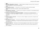
... computer. Connects to power the computer and charge the battery. 6 USB 3.0 connector - Provides faster data transmission between your computer. 31 Connects to the AC adapter to USB devices, such as a mouse, keyboard, printer, external drive, or MP3 player. Connects to view programs using a wired network. 4 Antenna-in connector (on your computer and USB devices. 7 Security cable slot - Connects to an external antenna (included) or coaxial cable (adapter included) to a TV for both 5.1 audio and video signals...
... computer. Connects to power the computer and charge the battery. 6 USB 3.0 connector - Provides faster data transmission between your computer. 31 Connects to the AC adapter to USB devices, such as a mouse, keyboard, printer, external drive, or MP3 player. Connects to view programs using a wired network. 4 Antenna-in connector (on your computer and USB devices. 7 Security cable slot - Connects to an external antenna (included) or coaxial cable (adapter included) to a TV for both 5.1 audio and video signals...

XPS 15 L502X Setup Guide
Page 37
... the keys. Using Your XPS Laptop 6 Keyboard/Backlit Keyboard (optional) - For more information, see "Touch Pad Gestures" on the keyboard. 35 The touch pad supports the Scroll, Flick, Zoom, and Rotate features. NOTE: To enable or disable the touch pad, press the keys on page 38. The backlit keyboard provides visibility in the notification area of a mouse to toggle the three lighting states (in the given order): • half keyboard brightness • full keyboard brightness • no lighting 7 Touch pad buttons (2) -
... the keys. Using Your XPS Laptop 6 Keyboard/Backlit Keyboard (optional) - For more information, see "Touch Pad Gestures" on the keyboard. 35 The touch pad supports the Scroll, Flick, Zoom, and Rotate features. NOTE: To enable or disable the touch pad, press the keys on page 38. The backlit keyboard provides visibility in the notification area of a mouse to toggle the three lighting states (in the given order): • half keyboard brightness • full keyboard brightness • no lighting 7 Touch pad buttons (2) -
XPS 15 L502X Setup Guide
Page 64
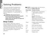
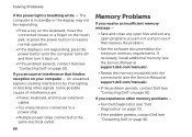
... Eight Display failure WARNING: Only trained service personnel should remove the computer cover. See the Service Manual at support.dell.com/manuals for assistance. 62 NOTE: To replace parts, see the Service Manual at support.dell.com. If you installed or replaced the memory module, ensure that the memory module is seated properly. If this occurs, write down the beep code and contact Dell (see "Contacting Dell" on page 91. BIOS ROM checksum failure Two No RAM...
... Eight Display failure WARNING: Only trained service personnel should remove the computer cover. See the Service Manual at support.dell.com/manuals for assistance. 62 NOTE: To replace parts, see the Service Manual at support.dell.com. If you installed or replaced the memory module, ensure that the memory module is seated properly. If this occurs, write down the beep code and contact Dell (see "Contacting Dell" on page 91. BIOS ROM checksum failure Two No RAM...
XPS 15 L502X Setup Guide
Page 68
... the display may not be responding. • Press a key on the keyboard, move the connected mouse or a finger on the touch pad, or press the power button to see "Contacting Dell" on page 91). If you encounter interference that resolves the problem. • See the software documentation for minimum memory requirements. If you experience other signals. If necessary, install additional memory (see the Service Manual at support.dell.com/manuals...
... the display may not be responding. • Press a key on the keyboard, move the connected mouse or a finger on the touch pad, or press the power button to see "Contacting Dell" on page 91). If you encounter interference that resolves the problem. • See the software documentation for minimum memory requirements. If you experience other signals. If necessary, install additional memory (see the Service Manual at support.dell.com/manuals...
XPS 15 L502X Setup Guide
Page 96
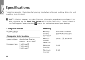
Computer Model Dell XPS L502X Computer Information System chipset Mobile Intel 6 series express chipset HM67 Processor type Intel Core i3 Intel Core i5 Intel Core i7 94 Memory Memory module connector Memory module capacities Minimum memory Maximum memory two user-accessible SODIMM connectors 1 GB, 2 GB, and 4 GB 2 GB 8 GB Specifications This section provides information that you may vary by region. To launch the Dell Support Center, click the icon...
Computer Model Dell XPS L502X Computer Information System chipset Mobile Intel 6 series express chipset HM67 Processor type Intel Core i3 Intel Core i5 Intel Core i7 94 Memory Memory module connector Memory module capacities Minimum memory Maximum memory two user-accessible SODIMM connectors 1 GB, 2 GB, and 4 GB 2 GB 8 GB Specifications This section provides information that you may vary by region. To launch the Dell Support Center, click the icon...


