Service Manual
Page 4
... 11: Removing the coin-cell battery 27 Prerequisites...27 Procedure...27 Chapter 12: Replacing the coin-cell battery 28 Procedure...28 Post-requisites...28 Chapter 13: Removing the heat sink 29 Prerequisites...29 Procedure...29 Chapter 14: Replacing the heat sink 30 Procedure...30 Post-requisites...30 Chapter 15: Removing the... the display assembly 39 Prerequisites...39 Procedure...39 Chapter 20: Replacing the display assembly 41 Procedure...41 Post-requisites...42 Chapter 21: Removing the headset port 43 Prerequisites...43 Procedure...43 4 Contents
... 11: Removing the coin-cell battery 27 Prerequisites...27 Procedure...27 Chapter 12: Replacing the coin-cell battery 28 Procedure...28 Post-requisites...28 Chapter 13: Removing the heat sink 29 Prerequisites...29 Procedure...29 Chapter 14: Replacing the heat sink 30 Procedure...30 Post-requisites...30 Chapter 15: Removing the... the display assembly 39 Prerequisites...39 Procedure...39 Chapter 20: Replacing the display assembly 41 Procedure...41 Post-requisites...42 Chapter 21: Removing the headset port 43 Prerequisites...43 Procedure...43 4 Contents
Service Manual
Page 5
Chapter 22: Replacing the headset port 45 Procedure...45 Post-requisites...46 Chapter 23: Removing the fans...47 Prerequisites...47 Procedure...47 Chapter 24: Replacing the fans 49 Procedure...49 Post-...
Chapter 22: Replacing the headset port 45 Procedure...45 Post-requisites...46 Chapter 23: Removing the fans...47 Prerequisites...47 Procedure...47 Chapter 24: Replacing the fans 49 Procedure...49 Post-...
Service Manual
Page 7
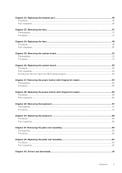
...and close all open applications. 2. When disconnecting cables, keep them by touching an unpainted metal surface, such as the metal at www.dell.com/ regulatory_compliance. For more safety best practices, see the documentation of your computer and certain components may differ from your operating system for...the cable itself. Shut down . Disconnect your computer depending on the configuration you ordered. See the safety instructions that the ports and the connectors are using a different operating system, see the Regulatory Compliance home page at the back of the computer.
...and close all open applications. 2. When disconnecting cables, keep them by touching an unpainted metal surface, such as the metal at www.dell.com/ regulatory_compliance. For more safety best practices, see the documentation of your computer and certain components may differ from your operating system for...the cable itself. Shut down . Disconnect your computer depending on the configuration you ordered. See the safety instructions that the ports and the connectors are using a different operating system, see the Regulatory Compliance home page at the back of the computer.
Service Manual
Page 10
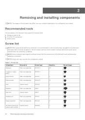
....4x1.7 2 System board Palm-rest assembly M1.6x2.5 10 Fans System board M1.6x3L 2 Speakers Palm-rest assembly M2x2 4 Heat sink System board M2x3 4 Headset port Palm-rest assembly M1.6x3 1 Display assembly Palm-rest assembly M2.5x4 4 Wireless antenna and System board M1.6x3L 1 camera cable bracket 10 Removing and...
....4x1.7 2 System board Palm-rest assembly M1.6x2.5 10 Fans System board M1.6x3L 2 Speakers Palm-rest assembly M2x2 4 Heat sink System board M2x3 4 Headset port Palm-rest assembly M1.6x3 1 Display assembly Palm-rest assembly M2.5x4 4 Wireless antenna and System board M1.6x3L 1 camera cable bracket 10 Removing and...
Service Manual
Page 12
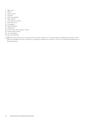
Left speaker 10. Battery 3. Right speaker 7. Solid-state drive 9. Headset port 12. Coin-cell battery 15. 1. System board 4. Display assembly 11. Heat-sink assembly NOTE: Dell provides a list of components and their part numbers for purchase options. 12 Removing and installing components... Base cover 2. Palm-rest assembly 6. Solid-state drive shield 8. Power button with fingerprint reader 13. Keyboard 5. Camera-cable bracket 14...
Left speaker 10. Battery 3. Right speaker 7. Solid-state drive 9. Headset port 12. Coin-cell battery 15. 1. System board 4. Display assembly 11. Heat-sink assembly NOTE: Dell provides a list of components and their part numbers for purchase options. 12 Removing and installing components... Base cover 2. Palm-rest assembly 6. Solid-state drive shield 8. Power button with fingerprint reader 13. Keyboard 5. Camera-cable bracket 14...
Service Manual
Page 43
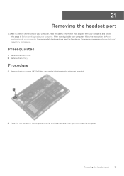
Remove the base cover. 2. Removing the headset port 43 Procedure 1. For more safety best practices, see the Regulatory Compliance home page at www.dell.com/ regulatory_compliance. Prerequisites 1. Place the top surface of the computer on a flat and clean surface, then open and close the computer. After working inside your ...
Remove the base cover. 2. Removing the headset port 43 Procedure 1. For more safety best practices, see the Regulatory Compliance home page at www.dell.com/ regulatory_compliance. Prerequisites 1. Place the top surface of the computer on a flat and clean surface, then open and close the computer. After working inside your ...
Service Manual
Page 44
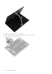
Lift the headset port from the system board. 4. Disconnect the headset-port cable from the system board. 44 Removing the headset port Remove the screw (M1.6x3) that secures the headset port to the palm-rest assembly. 5. 3.
Lift the headset port from the system board. 4. Disconnect the headset-port cable from the system board. 44 Removing the headset port Remove the screw (M1.6x3) that secures the headset port to the palm-rest assembly. 5. 3.
Service Manual
Page 45
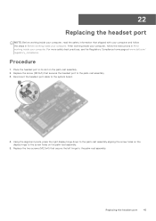
...inside your computer, follow the steps in Before working inside your computer. Replace the two screws (M2.5x4) that secures the headset port to the palm-rest assembly. Using the alignment posts, press the right display hinge down to the palm-rest assembly aligning the screw... the left hinge to the palm-rest assembly 3. Replacing the headset port 45 For more safety best practices, see the Regulatory Compliance home page at www.dell.com/ regulatory_compliance. Procedure 1. 22 Replacing the headset port NOTE: Before working inside your computer, read the safety information that ...
...inside your computer, follow the steps in Before working inside your computer. Replace the two screws (M2.5x4) that secures the headset port to the palm-rest assembly. Using the alignment posts, press the right display hinge down to the palm-rest assembly aligning the screw... the left hinge to the palm-rest assembly 3. Replacing the headset port 45 For more safety best practices, see the Regulatory Compliance home page at www.dell.com/ regulatory_compliance. Procedure 1. 22 Replacing the headset port NOTE: Before working inside your computer, read the safety information that ...
Service Manual
Page 46
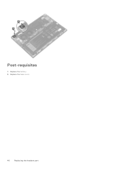
Replace the battery. 2. Post-requisites 1. Replace the base cover. 46 Replacing the headset port
Replace the battery. 2. Post-requisites 1. Replace the base cover. 46 Replacing the headset port
Service Manual
Page 51
... from the system board. 3. For more safety best practices, see the Regulatory Compliance home page at www.dell.com/ regulatory_compliance. You must enter the Service Tag in After working inside your computer. Disconnect the headset-port cable from the system board. 7. NOTE: Replacing the system board removes any changes you replace the...
... from the system board. 3. For more safety best practices, see the Regulatory Compliance home page at www.dell.com/ regulatory_compliance. You must enter the Service Tag in After working inside your computer. Disconnect the headset-port cable from the system board. 7. NOTE: Replacing the system board removes any changes you replace the...
Service Manual
Page 53
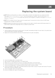
...replace the system board. Connect the fingerprint-reader cable to the system board and close the latch to the system board. Connect the headset-port cable to secure the cable. 8. You must make the appropriate changes again after you replace the system board. NOTE: Your computer's ... assembly and align the screw holes on the system board. 5. For more safety best practices, see the Regulatory Compliance home page at www.dell.com/ regulatory_compliance. Connect the speaker cable to the system board. 6. Replace the two screws (M1.6x2.5) that secure the display cable bracket...
...replace the system board. Connect the fingerprint-reader cable to the system board and close the latch to the system board. Connect the headset-port cable to secure the cable. 8. You must make the appropriate changes again after you replace the system board. NOTE: Your computer's ... assembly and align the screw holes on the system board. 5. For more safety best practices, see the Regulatory Compliance home page at www.dell.com/ regulatory_compliance. Connect the speaker cable to the system board. 6. Replace the two screws (M1.6x2.5) that secure the display cable bracket...
Service Manual
Page 59
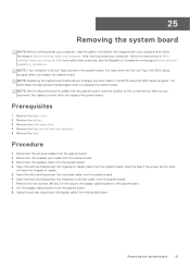
.... 2. Remove the battery. 3. Remove the keyboard. For more safety best practices, see the Regulatory Compliance home page at www.dell.com/ regulatory_compliance. Remove the speakers. 4. Remove the system board. 8. Remove the headset port. 6. Procedure After performing all the pre-requisites, we are left with fingerprint reader. 9. Remove the fans. 7. Remove the power...
.... 2. Remove the battery. 3. Remove the keyboard. For more safety best practices, see the Regulatory Compliance home page at www.dell.com/ regulatory_compliance. Remove the speakers. 4. Remove the system board. 8. Remove the headset port. 6. Procedure After performing all the pre-requisites, we are left with fingerprint reader. 9. Remove the fans. 7. Remove the power...
Service Manual
Page 60
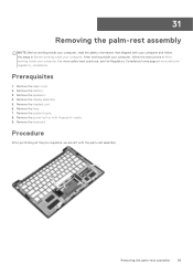
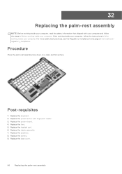
...information that shipped with fingerprint reader. 3. For more safety best practices, see the Regulatory Compliance home page at www.dell.com/ regulatory_compliance. Procedure Place the palm-rest assembly face down on a clean and flat surface. Replace the power button... with your computer and follow the instructions in Before working inside your computer. Replace the headset port. 6. Replace the fans. 5. Replace the battery. 9. Replace the keyboard. 2. Replace the display assembly. 7. Replace the speakers. 8. ...
...information that shipped with fingerprint reader. 3. For more safety best practices, see the Regulatory Compliance home page at www.dell.com/ regulatory_compliance. Procedure Place the palm-rest assembly face down on a clean and flat surface. Replace the power button... with your computer and follow the instructions in Before working inside your computer. Replace the headset port. 6. Replace the fans. 5. Replace the battery. 9. Replace the keyboard. 2. Replace the display assembly. 7. Replace the speakers. 8. ...
Service Manual
Page 65
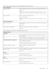
... HH/MM/SS 24-hour format. Changes to the time take effect immediately. Changes to the date take effect immediately. By default, Enable External USB Ports is selected. By default, Enable USB Boot Support is selected. By default, Enable Camera is selected. Time Sets the computer time in MM/DD/YYYY...
... HH/MM/SS 24-hour format. Changes to the time take effect immediately. Changes to the date take effect immediately. By default, Enable External USB Ports is selected. By default, Enable USB Boot Support is selected. By default, Enable Camera is selected. Time Sets the computer time in MM/DD/YYYY...
Service Manual
Page 66
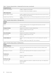
Table 8. Table 9. Default: ON Full Screen Logo Full Screen Logo Enabled or disabled the computer to external USB port. Default: OFF 66 System setup Enable or disable booting from USB mass storage devices such as external hard drive, optical drive, and ... state. Default: ON Drive Information M.2 PCIe SSD Displays the information of onboard drives. USB configuration Enable USB Boot Support Enable External USB Ports Enable or disable booting from USB mass storage devices connected to display full screen logo if the image match screen resolution. Enables or disables ...
Table 8. Table 9. Default: ON Full Screen Logo Full Screen Logo Enabled or disabled the computer to external USB port. Default: OFF 66 System setup Enable or disable booting from USB mass storage devices such as external hard drive, optical drive, and ... state. Default: ON Drive Information M.2 PCIe SSD Displays the information of onboard drives. USB configuration Enable USB Boot Support Enable External USB Ports Enable or disable booting from USB mass storage devices connected to display full screen logo if the image match screen resolution. Enables or disables ...
Setup and Specifications
Page 3
Contents Chapter 1: Set up your XPS 13 9305 4 Chapter 2: Views of XPS 13 9305 6 Front...6 Right...6 Left...7 Base...8 Display...8 Bottom...9 Chapter 3: Specifications of XPS 13 9305 10 Dimensions and weight...10 Processor...10 Chipset...11 Operating system...11 Memory...11 External ports...12 Wireless module...12 Audio...13 Storage...13 Media-card reader...14 Keyboard...14 Camera...14 Touchpad...15 Power adapter...15...
Contents Chapter 1: Set up your XPS 13 9305 4 Chapter 2: Views of XPS 13 9305 6 Front...6 Right...6 Left...7 Base...8 Display...8 Bottom...9 Chapter 3: Specifications of XPS 13 9305 10 Dimensions and weight...10 Processor...10 Chipset...11 Operating system...11 Memory...11 External ports...12 Wireless module...12 Audio...13 Storage...13 Media-card reader...14 Keyboard...14 Camera...14 Touchpad...15 Power adapter...15...
Setup and Specifications
Page 4
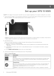
... at www.dell.com/support. 1 Set up your XPS 13 9305 NOTE: The images in with the operating system. NOTE: The battery may differ from the Windows Start menu-Recommended. Locate Dell apps Resources Description My Dell Centralized location for the wireless network access when prompted. ● If connected to the Thunderbolt 4 (USB Type-C) port with Power...
... at www.dell.com/support. 1 Set up your XPS 13 9305 NOTE: The images in with the operating system. NOTE: The battery may differ from the Windows Start menu-Recommended. Locate Dell apps Resources Description My Dell Centralized location for the wireless network access when prompted. ● If connected to the Thunderbolt 4 (USB Type-C) port with Power...
Setup and Specifications
Page 6
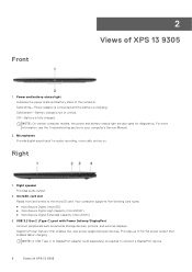
...sound input for diagnostics. Right 1. microSD-card slot Reads from and writes to connect a DisplayPort device. 6 Views of XPS 13 9305 1. Provides up to DisplayPort adapter (sold separately) is low or critical. NOTE: A USB Type-C to 5V/3A power... (Type-C) port with Power Delivery/DisplayPort Connect peripherals such as external storage devices, printers, and external displays. Solid amber-Battery charge is required to the microSD card. For more information, see the Troubleshooting section in your computer's Service Manual. 2. Front 2 Views of XPS 13 9305 NOTE: On...
...sound input for diagnostics. Right 1. microSD-card slot Reads from and writes to connect a DisplayPort device. 6 Views of XPS 13 9305 1. Provides up to DisplayPort adapter (sold separately) is low or critical. NOTE: A USB Type-C to 5V/3A power... (Type-C) port with Power Delivery/DisplayPort Connect peripherals such as external storage devices, printers, and external displays. Solid amber-Battery charge is required to the microSD card. For more information, see the Troubleshooting section in your computer's Service Manual. 2. Front 2 Views of XPS 13 9305 NOTE: On...
Setup and Specifications
Page 7
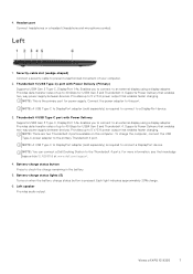
...ports. Thunderbolt 4 (USB Type-C) port with Power Delivery Supports USB4 Gen 3 Type-C, DisplayPort 1.4a. NOTE: This is required to connect a DisplayPort device. Provides data transfer rates of your computer. 2. Provides up to an external display using a display adapter. Provides data transfer rates of XPS 13 9305... For more information, see the knowledge base article SLN286158 at www.dell.com/support. 4. To charge the computer, connect the USB Type-C power adapter to a DisplayPort device. 3. Headset port Connect headphones or a headset (headphone and microphone combo). Left speaker...
...ports. Thunderbolt 4 (USB Type-C) port with Power Delivery Supports USB4 Gen 3 Type-C, DisplayPort 1.4a. NOTE: This is required to connect a DisplayPort device. Provides data transfer rates of your computer. 2. Provides up to an external display using a display adapter. Provides data transfer rates of XPS 13 9305... For more information, see the knowledge base article SLN286158 at www.dell.com/support. 4. To charge the computer, connect the USB Type-C power adapter to a DisplayPort device. 3. Headset port Connect headphones or a headset (headphone and microphone combo). Left speaker...

Setup and Specifications
Page 12
... Wireless module The following table lists the external ports on your XPS 13 9305. External ports The following table lists the Wireless Local Area Network (WLAN) module supported on your XPS 13 9305. External ports Description USB ports Values ● One USB 3.2 Gen 2 (Type-C) port with Power Delivery/ DisplayPort ● Two Thunderbolt 4 USB Type-C ports with Power Delivery NOTE: A USB Type-C to...
... Wireless module The following table lists the external ports on your XPS 13 9305. External ports The following table lists the Wireless Local Area Network (WLAN) module supported on your XPS 13 9305. External ports Description USB ports Values ● One USB 3.2 Gen 2 (Type-C) port with Power Delivery/ DisplayPort ● Two Thunderbolt 4 USB Type-C ports with Power Delivery NOTE: A USB Type-C to...


