User Guide
Page 3
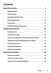
... Contents 5 Product Features 6 Identifying Parts and Controls 7 Monitor Specifications 10 Plug-and-Play 21 LCD Monitor Quality and Pixel Policy 21 Setting Up the Monitor 22 Installing the Arm 22 Organizing Your Cables 29 Using the Tilt, Swivel, Pivot, Vertical and Horizontal Extension... 30 Adjusting the Rotation Display Settings of Your System 32 Connecting Your Monitor 33 Removing the Monitor Arm 36 Wall Mounting (Optional 37 Operating the Monitor 38 Turning on the Monitor 38 Using the Front Panel Controls 38 Using the On-Screen Display (OSD) Menu 41...
... Contents 5 Product Features 6 Identifying Parts and Controls 7 Monitor Specifications 10 Plug-and-Play 21 LCD Monitor Quality and Pixel Policy 21 Setting Up the Monitor 22 Installing the Arm 22 Organizing Your Cables 29 Using the Tilt, Swivel, Pivot, Vertical and Horizontal Extension... 30 Adjusting the Rotation Display Settings of Your System 32 Connecting Your Monitor 33 Removing the Monitor Arm 36 Wall Mounting (Optional 37 Operating the Monitor 38 Turning on the Monitor 38 Using the Front Panel Controls 38 Using the On-Screen Display (OSD) Menu 41...

User Guide
Page 4
only) and Other Regulatory Information 59 Contacting Dell 59 Setting Up Your Monitor 60 Maintenance Guidelines 62 4 | Contents Troubleshooting 53 Self-Test 53 Built-in Diagnostics 55 Common Problems 56 Product Specific Problems 57 Mobile High-Definition Link (MHL) Specific Problems 58 Appendix 59 Safety Instructions 59 FCC Notices (U.S.
only) and Other Regulatory Information 59 Contacting Dell 59 Setting Up Your Monitor 60 Maintenance Guidelines 62 4 | Contents Troubleshooting 53 Self-Test 53 Built-in Diagnostics 55 Common Problems 56 Product Specific Problems 57 Mobile High-Definition Link (MHL) Specific Problems 58 Appendix 59 Safety Instructions 59 FCC Notices (U.S.

User Guide
Page 5
Make sure that you have received all the components and contact Dell if something is missing. Some features or media may not be optional and may be available in certain countries. About Your Monitor Package Contents Your monitor ships with your monitor. Monitor Arm riser Arm base Allen key Power cable (varies by country) About Your Monitor | 5 NOTE: Some items may not ship with the components shown below.
Make sure that you have received all the components and contact Dell if something is missing. Some features or media may not be optional and may be available in certain countries. About Your Monitor Package Contents Your monitor ships with your monitor. Monitor Arm riser Arm base Allen key Power cable (varies by country) About Your Monitor | 5 NOTE: Some items may not ship with the components shown below.
User Guide
Page 6
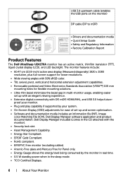
... sleep mode. • TCO Certified Displays. 6 | About Your Monitor Dell Display Manager included (comes in multi-monitor usage, enabling easier set -up with an elegant viewing experience. • Extensive digital connectivity with the monitor). • Security lock slot. • Asset Management Capability. &#... the USB ports on the monitor) DP cable (DP to mDP) • Drivers and documentation media • Quick Setup Guide • Safety and Regulatory Information • Factory Calibration Report Product Features The Dell UltraSharp U2417HA monitor has an active matrix, thinfilm...
... sleep mode. • TCO Certified Displays. 6 | About Your Monitor Dell Display Manager included (comes in multi-monitor usage, enabling easier set -up with an elegant viewing experience. • Extensive digital connectivity with the monitor). • Security lock slot. • Asset Management Capability. &#... the USB ports on the monitor) DP cable (DP to mDP) • Drivers and documentation media • Quick Setup Guide • Safety and Regulatory Information • Factory Calibration Report Product Features The Dell UltraSharp U2417HA monitor has an active matrix, thinfilm...

User Guide
Page 7
Identifying Parts and Controls Front view Label 1 2 Description Function buttons (For more information, see Operating the Monitor) Power on/off button (with LED indicator) About Your Monitor | 7
Identifying Parts and Controls Front view Label 1 2 Description Function buttons (For more information, see Operating the Monitor) Power on/off button (with LED indicator) About Your Monitor | 7
User Guide
Page 8
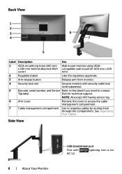
... 2 Regulatory label Lists the regulatory approvals. 3 Arm release button Release arm from monitor. 4 Security lock slot Secures monitor with lightning icon is for technical support. Back View Label Description Use 1 VESA mountiong holes (100 mm... Wall mount monitor using VESA- NOTE: All except APJ having service tag. 6 Arm cover Remove the cover to access the cable management compartment. 7 Cable management compartment Use to contact Tag label Dell...
... 2 Regulatory label Lists the regulatory approvals. 3 Arm release button Release arm from monitor. 4 Security lock slot Secures monitor with lightning icon is for technical support. Back View Label Description Use 1 VESA mountiong holes (100 mm... Wall mount monitor using VESA- NOTE: All except APJ having service tag. 6 Arm cover Remove the cover to access the cable management compartment. 7 Cable management compartment Use to contact Tag label Dell...

User Guide
Page 9
...device. DP connector (out) DP output for DP MST Function". To enable MST, refer to the computer and USB upstream connector on the monitor. Only supports 2-channel audio. USB downstream ports (2) Connect your computer with HDMI cable or MHL devices with MHL cable (optional). Arm lock.... mDP connector (in the MST chain. Once this connector after you can cause hearing damage or loss. Audio line-out port Connect speakers to the monitor using a M3 x 6 mm screw (screw not included). NOTE: The audio line-out port does not support headphones. Bottom View Label 1 2 3 4 5 6 7 8 ...
...device. DP connector (out) DP output for DP MST Function". To enable MST, refer to the computer and USB upstream connector on the monitor. Only supports 2-channel audio. USB downstream ports (2) Connect your computer with HDMI cable or MHL devices with MHL cable (optional). Arm lock.... mDP connector (in the MST chain. Once this connector after you can cause hearing damage or loss. Audio line-out port Connect speakers to the monitor using a M3 x 6 mm screw (screw not included). NOTE: The audio line-out port does not support headphones. Bottom View Label 1 2 3 4 5 6 7 8 ...

User Guide
Page 10
Monitor Specifications Flat Panel Specifications Screen type Panel type Viewable image Diagonal Active Area Horizontal Vertical Area Pixel pitch Viewing angle Horizontal Vertical Luminance output Contrast ... 75 Hz (DP/HDMI) 24 Hz to 60 Hz (MHL) 1920 x 1080 at 60 Hz 480i, 480p, 576i, 576p, 720p, 1080i, 1080p 10 | About Your Monitor
Monitor Specifications Flat Panel Specifications Screen type Panel type Viewable image Diagonal Active Area Horizontal Vertical Area Pixel pitch Viewing angle Horizontal Vertical Luminance output Contrast ... 75 Hz (DP/HDMI) 24 Hz to 60 Hz (MHL) 1920 x 1080 at 60 Hz 480i, 480p, 576i, 576p, 720p, 1080i, 1080p 10 | About Your Monitor
User Guide
Page 12
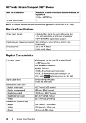
....6 mm (21.17 inches) 46.1 mm (1.81 inches) 12 | About Your Monitor MST Multi-Stream Transport (MST) Modes MST Source Monitor 1920 x 1080/60 Hz Maximum number of external monitor that can be supported 1920 x 1080/60 Hz 2 NOTE: Maximum external monitor resolution supported is for each differential line Per differential line at 100...
....6 mm (21.17 inches) 46.1 mm (1.81 inches) 12 | About Your Monitor MST Multi-Stream Transport (MST) Modes MST Source Monitor 1920 x 1080/60 Hz Maximum number of external monitor that can be supported 1920 x 1080/60 Hz 2 NOTE: Maximum external monitor resolution supported is for each differential line Per differential line at 100...

User Guide
Page 13
...) 5% to 90% (non-condensing) 5,000 m (16,404 ft) (maximum) 12,192 m (40,000 ft) (maximum) 232 BTU/hour (maximum) 64.8 BTU/hour (typical) About Your Monitor | 13 Arm dimensions Height Width Depth Weight Weight with packaging Weight with arm assembly and cables Weight without arm assembly (For wall mount or VESA...
...) 5% to 90% (non-condensing) 5,000 m (16,404 ft) (maximum) 12,192 m (40,000 ft) (maximum) 232 BTU/hour (maximum) 64.8 BTU/hour (typical) About Your Monitor | 13 Arm dimensions Height Width Depth Weight Weight with packaging Weight with arm assembly and cables Weight without arm assembly (For wall mount or VESA...

User Guide
Page 14
... on the software, components and peripherals you ordered and shall have VESA's DPM-compliant video card or software installed in your PC, the monitor can only be achieved by disconnecting the AC mains cable from the keyboard, mouse, or other input devices, the...implied. If you press any button in the active-off Horizontal Vertical Video Power Indicator Sync Sync Active Active Active White Inactive - NOTE: This monitor is tested at 230 Volts / 50 Hz. This is referred to as to accuracy or completeness is informational only and reflects laboratory performance. Accordingly,...
... on the software, components and peripherals you ordered and shall have VESA's DPM-compliant video card or software installed in your PC, the monitor can only be achieved by disconnecting the AC mains cable from the keyboard, mouse, or other input devices, the...implied. If you press any button in the active-off Horizontal Vertical Video Power Indicator Sync Sync Active Active Active White Inactive - NOTE: This monitor is tested at 230 Volts / 50 Hz. This is referred to as to accuracy or completeness is informational only and reflects laboratory performance. Accordingly,...

User Guide
Page 15
Pin Assignments DP connector (in) Pin number 20-pin side of the connected signal cable 1 ML3(n) 2 GND 3 ML3(p) 4 ML2(n) 5 GND 6 ML2(p) 7 ML1(u) 8 GND 9 ML1(p) 10 ML0(n) 11 GND 12 ML0(p) 13 CONFIG1 14 CONFIG2 15 AUX CH (p) 16 GND 17 AUX CH (n) 18 Hot Plug Detect 19 Return 20 DP_PWR About Your Monitor | 15
Pin Assignments DP connector (in) Pin number 20-pin side of the connected signal cable 1 ML3(n) 2 GND 3 ML3(p) 4 ML2(n) 5 GND 6 ML2(p) 7 ML1(u) 8 GND 9 ML1(p) 10 ML0(n) 11 GND 12 ML0(p) 13 CONFIG1 14 CONFIG2 15 AUX CH (p) 16 GND 17 AUX CH (n) 18 Hot Plug Detect 19 Return 20 DP_PWR About Your Monitor | 15

User Guide
Page 16
DP connector (out) Pin number 20-pin side of the connected signal cable 1 ML0(p) 2 GND 3 ML0(n) 4 ML1(p) 5 GND 6 ML1(n) 7 ML2(p) 8 GND 9 ML2(n) 10 ML3(p) 11 GND 12 ML3(n) 13 CONFIG1 14 CONFIG2 15 AUX CH(p) 16 GND 17 AUX CH(n) 18 Hot Plug Detect 19 Return 20 DP_PWR 16 | About Your Monitor
DP connector (out) Pin number 20-pin side of the connected signal cable 1 ML0(p) 2 GND 3 ML0(n) 4 ML1(p) 5 GND 6 ML1(n) 7 ML2(p) 8 GND 9 ML2(n) 10 ML3(p) 11 GND 12 ML3(n) 13 CONFIG1 14 CONFIG2 15 AUX CH(p) 16 GND 17 AUX CH(n) 18 Hot Plug Detect 19 Return 20 DP_PWR 16 | About Your Monitor

User Guide
Page 17
mDP connector Pin number 20-pin side of the connected signal cable 1 GND 2 Hot Plug Detect 3 ML3 (n) 4 CONFIG1 5 ML3 (p) 6 CONFIG2 7 GND 8 GND 9 ML2 (n) 10 ML0 (p) 11 ML2 (p) 12 ML0 (p) 13 GND 14 GND 15 ML1 (n) 16 AUX (p) 17 ML1 (p) 18 AUX (n) 19 GND 20 DP_PWR About Your Monitor | 17
mDP connector Pin number 20-pin side of the connected signal cable 1 GND 2 Hot Plug Detect 3 ML3 (n) 4 CONFIG1 5 ML3 (p) 6 CONFIG2 7 GND 8 GND 9 ML2 (n) 10 ML0 (p) 11 ML2 (p) 12 ML0 (p) 13 GND 14 GND 15 ML1 (n) 16 AUX (p) 17 ML1 (p) 18 AUX (n) 19 GND 20 DP_PWR About Your Monitor | 17

User Guide
Page 18
HDMI connector Pin number 1 2 3 4 5 6 7 8 9 10 11 12 13 14 15 16 17 18 19 19-pin side of the connected signal cable TMDS DATA 2+ TMDS DATA 2 SHIELD TMDS DATA 2TMDS DATA 1+ TMDS DATA 1 SHIELD TMDS DATA 1TMDS DATA 0+ TMDS DATA 0 SHIELD TMDS DATA 0TMDS CLOCK+ TMDS CLOCK SHIELD TMDS CLOCKCEC Reserved (N.C. on device) DDC CLOCK (SCL) DDC DATA (SDA) DDC/CEC Ground +5 V POWER HOT PLUG DETECT 18 | About Your Monitor
HDMI connector Pin number 1 2 3 4 5 6 7 8 9 10 11 12 13 14 15 16 17 18 19 19-pin side of the connected signal cable TMDS DATA 2+ TMDS DATA 2 SHIELD TMDS DATA 2TMDS DATA 1+ TMDS DATA 1 SHIELD TMDS DATA 1TMDS DATA 0+ TMDS DATA 0 SHIELD TMDS DATA 0TMDS CLOCK+ TMDS CLOCK SHIELD TMDS CLOCKCEC Reserved (N.C. on device) DDC CLOCK (SCL) DDC DATA (SDA) DDC/CEC Ground +5 V POWER HOT PLUG DETECT 18 | About Your Monitor

User Guide
Page 19
MHL connector Pin number 19-pin side of the connected signal cable 1 N/C 2 CD_SENSE 3 N/C 4 N/C 5 TMDS_GND 6 N/C 7 MHL+ 8 MHL_Shield 9 MHL- 10 N/C 11 TMDS_GND 12 N/C 13 N/C 14 N/C 15 CD_PULLUP 16 N/C 17 VBUS_CBUS_GND 18 VBUS 19 CBUS 2Shell Shield About Your Monitor | 19
MHL connector Pin number 19-pin side of the connected signal cable 1 N/C 2 CD_SENSE 3 N/C 4 N/C 5 TMDS_GND 6 N/C 7 MHL+ 8 MHL_Shield 9 MHL- 10 N/C 11 TMDS_GND 12 N/C 13 N/C 14 N/C 15 CD_PULLUP 16 N/C 17 VBUS_CBUS_GND 18 VBUS 19 CBUS 2Shell Shield About Your Monitor | 19

User Guide
Page 20
...USB upstream port USB downstream port Pin number 1 2 3 4 5 6 7 8 9 Shell Signal name VBUS DD+ GND StdB_SSTXStdB_SSTX+ GND_DRAIN StdB_SSRXStdB_SSRX+ Shield 20 | About Your Monitor Pin number 1 2 3 4 5 6 7 8 9 Shell Signal name VBUS DD+ GND StdA_SSRXStdA_SSRX+ GND_DRAIN StdA_SSTXStdA_SSTX+ Shield NOTE: Up to 2 A on , the attached peripherals...a few seconds to 0.9 A on or in the power save mode. the one on your monitor. NOTE: The monitor's USB ports work only when the monitor is BC 1.2 compatible. up to resume normal functionality. Universal Serial Bus (USB) This section...
...USB upstream port USB downstream port Pin number 1 2 3 4 5 6 7 8 9 Shell Signal name VBUS DD+ GND StdB_SSTXStdB_SSTX+ GND_DRAIN StdB_SSRXStdB_SSRX+ Shield 20 | About Your Monitor Pin number 1 2 3 4 5 6 7 8 9 Shell Signal name VBUS DD+ GND StdA_SSRXStdA_SSRX+ GND_DRAIN StdA_SSTXStdA_SSTX+ Shield NOTE: Up to 2 A on , the attached peripherals...a few seconds to 0.9 A on or in the power save mode. the one on your monitor. NOTE: The monitor's USB ports work only when the monitor is BC 1.2 compatible. up to resume normal functionality. Universal Serial Bus (USB) This section...

User Guide
Page 21
... process, it is not uncommon for one or more information about changing the monitor settings, see Dell support site at: http://www.dell.com/support/monitors. you can configure itself and optimize the monitor settings. The monitor automatically provides the computer system with its extended display identification data (EDID) using display data channel (DDC) protocols so...
... process, it is not uncommon for one or more information about changing the monitor settings, see Dell support site at: http://www.dell.com/support/monitors. you can configure itself and optimize the monitor settings. The monitor automatically provides the computer system with its extended display identification data (EDID) using display data channel (DDC) protocols so...

User Guide
Page 22
NOTE: The arm installing instruction is shipped from the factory. Installing the Arm Base There are detached when the monitor is applicable to the arm shipped with gap between C. Others A. Table with open edge • Install the 2 screws either on top row or the... of table configurations which the arm base could be installed: A. Table with partition with the monitor. For other mounting solutions (optional), please refer to secure in place. 22 | Setting Up the Monitor Setting Up the Monitor Installing the Arm NOTE: The arm riser and arm base are a few types of arm ...
NOTE: The arm installing instruction is shipped from the factory. Installing the Arm Base There are detached when the monitor is applicable to the arm shipped with gap between C. Others A. Table with open edge • Install the 2 screws either on top row or the... of table configurations which the arm base could be installed: A. Table with partition with the monitor. For other mounting solutions (optional), please refer to secure in place. 22 | Setting Up the Monitor Setting Up the Monitor Installing the Arm NOTE: The arm riser and arm base are a few types of arm ...

User Guide
Page 23
B. Table with partition with the underside of table. • Slide the arm base assembly completely into the table. • Tighten the thumbscrew until the clamp disc is fully in contact with gap between • Insert the arm base bracket through the gap between table and partition. Setting Up the Monitor | 23
B. Table with partition with the underside of table. • Slide the arm base assembly completely into the table. • Tighten the thumbscrew until the clamp disc is fully in contact with gap between • Insert the arm base bracket through the gap between table and partition. Setting Up the Monitor | 23


