
Service Manual
Page 11
...assembly to Contents Page Support Assembly Dell Studio One 19/1909 Service Manual Removing the Support Assembly Replacing the Support Assembly WARNING: Before working inside your computer, read the safety information that shipped with your computer. Remove the hard drive (see Removing the Inverter). 7. Remove the side I/O ...such as the computer stand). Remove the optical drive (see Removing the Power Supply Unit). 4. Disconnect the following cables from the LCD panel: l LVDS cable from LVDS connector l touch pad cable from the touch pad connector l touch panel cable from the touch ...
...assembly to Contents Page Support Assembly Dell Studio One 19/1909 Service Manual Removing the Support Assembly Replacing the Support Assembly WARNING: Before working inside your computer, read the safety information that shipped with your computer. Remove the hard drive (see Removing the Inverter). 7. Remove the side I/O ...such as the computer stand). Remove the optical drive (see Removing the Power Supply Unit). 4. Disconnect the following cables from the LCD panel: l LVDS cable from LVDS connector l touch pad cable from the touch pad connector l touch panel cable from the touch ...

Service Manual
Page 20
... Begin. 2. Remove the shield (see the Regulatory Compliance Homepage at www.dell.com/regulatory_compliance. Disconnect the two cables that connect the inverter to Contents Page Inverter Dell Studio One 19/1909 Service Manual Removing the Inverter Replacing the Inverter WARNING: Before working inside your computer. Back to the LCD panel. 12. For additional safety best practices information, see Removing the Shield...
... Begin. 2. Remove the shield (see the Regulatory Compliance Homepage at www.dell.com/regulatory_compliance. Disconnect the two cables that connect the inverter to Contents Page Inverter Dell Studio One 19/1909 Service Manual Removing the Inverter Replacing the Inverter WARNING: Before working inside your computer. Back to the LCD panel. 12. For additional safety best practices information, see Removing the Shield...
Service Manual
Page 50
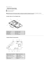
Back to Contents Page Technical Overview Dell Studio One 19/1909 Service Manual Inside View of Your Studio One 1 processor fan 3 left speaker 5 hard drive 7 optical drive 2 back I/O panel 4 side I/O panel 6 stand 8 right speaker System Board Components 1 password jumper (CLR_PSWD) 3 back I/O panel, PCI Express x4 connector (PCIE_4X_1) 5 inverter connector (INVERTER) 7 optical drive connector (ODD_POWER) 2 LCD connector (LVDS) 4 power supply unit connector...
Back to Contents Page Technical Overview Dell Studio One 19/1909 Service Manual Inside View of Your Studio One 1 processor fan 3 left speaker 5 hard drive 7 optical drive 2 back I/O panel 4 side I/O panel 6 stand 8 right speaker System Board Components 1 password jumper (CLR_PSWD) 3 back I/O panel, PCI Express x4 connector (PCIE_4X_1) 5 inverter connector (INVERTER) 7 optical drive connector (ODD_POWER) 2 LCD connector (LVDS) 4 power supply unit connector...


