Service Manual
Page 1
...: A CAUTION indicates either trademarks or registered trademarks of Dell Inc. Model MTF March 2009 Rev. Dell Studio One 19/1909 Service Manual Technical Overview Before You Begin Computer Cover Shield Microphone Stand Memory Module(s) Back I/O Panel Processor Fan and Heat Sink Processor Speakers Drives Cards Inverter System Fan and Heat Sink Assembly Side I/O Panel Power Supply Unit...
...: A CAUTION indicates either trademarks or registered trademarks of Dell Inc. Model MTF March 2009 Rev. Dell Studio One 19/1909 Service Manual Technical Overview Before You Begin Computer Cover Shield Microphone Stand Memory Module(s) Back I/O Panel Processor Fan and Heat Sink Processor Speakers Drives Cards Inverter System Fan and Heat Sink Assembly Side I/O Panel Power Supply Unit...
Service Manual
Page 5
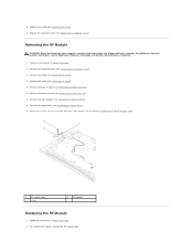
... Back I/O Panel). 6. Remove the back I/O panel (see Removing the Shield). 4. For additional safety best practices information, see Removing the Processor Fan). 7. Remove the processor fan (see the Regulatory Compliance Homepage at www.dell.com/regulatory_compliance. 1. 6. Remove the screw securing the radio frequency (RF) module, flip the module and disconnect the RF module cable...
... Back I/O Panel). 6. Remove the back I/O panel (see Removing the Shield). 4. For additional safety best practices information, see Removing the Processor Fan). 7. Remove the processor fan (see the Regulatory Compliance Homepage at www.dell.com/regulatory_compliance. 1. 6. Remove the screw securing the radio frequency (RF) module, flip the module and disconnect the RF module cable...
Service Manual
Page 6
... hole on the chassis. 4. Replace the optical drive (see Replacing the Computer Cover). Replace the computer cover (see Replacing the Optical Drive). 6. Replace the processor fan (see Replacing the Right Speaker). 7. Replace the screw that secures the RF module. 5. Replace the right speaker (see Replacing the Processor...
... hole on the chassis. 4. Replace the optical drive (see Replacing the Computer Cover). Replace the computer cover (see Replacing the Optical Drive). 6. Replace the processor fan (see Replacing the Right Speaker). 7. Replace the screw that secures the RF module. 5. Replace the right speaker (see Replacing the Processor...
Service Manual
Page 14
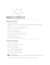
... to the hard drive carrier. 5. Slide the hard drive carrier into the grooves in Before You Begin. 2. Remove the shield (see Removing the Processor Fan). 7. Remove the processor fan (see Removing the Shield). 4. Replace the four screws that secure the hard drive to the hard drive. 6. Remove the back I/O panel (see Replacing...
... to the hard drive carrier. 5. Slide the hard drive carrier into the grooves in Before You Begin. 2. Remove the shield (see Removing the Processor Fan). 7. Remove the processor fan (see Removing the Shield). 4. Replace the four screws that secure the hard drive to the hard drive. 6. Remove the back I/O panel (see Replacing...
Service Manual
Page 15
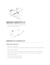
...check the documentation that secure the optical drive. 5. Reconnect the optical drive connector. 7. Replace the right speaker (see Replacing the Processor Fan). Follow the procedures in Before You Begin. 2. Align the screw holes on the optical drive with the screw holes on the optical... four screws that accompanied the drive to the optical drive carrier. 11. Slide the drive into the optical drive carrier. 4. Replace the processor fan (see Replacing the Right Speaker). 8. Slide the optical drive out of the optical drive carrier. 1 optical drive carrier 2 screws (4) Replacing...
...check the documentation that secure the optical drive. 5. Reconnect the optical drive connector. 7. Replace the right speaker (see Replacing the Processor Fan). Follow the procedures in Before You Begin. 2. Align the screw holes on the optical drive with the screw holes on the optical... four screws that accompanied the drive to the optical drive carrier. 11. Slide the drive into the optical drive carrier. 4. Replace the processor fan (see Replacing the Right Speaker). 8. Slide the optical drive out of the optical drive carrier. 1 optical drive carrier 2 screws (4) Replacing...

Service Manual
Page 17
...the Setup Guide. Remove the shield (see the Regulatory Compliance Homepage at www.dell.com/regulatory_compliance. The oils in Before You Begin. 2. Back to Contents Page Processor Fan and Heat Sink Dell Studio One 19/1909 Service Manual Removing the Heat Sink Replacing the Heat Sink Removing the ...Processor Fan Replacing the Processor Fan WARNING: Before working inside your computer, read the safety information...
...the Setup Guide. Remove the shield (see the Regulatory Compliance Homepage at www.dell.com/regulatory_compliance. The oils in Before You Begin. 2. Back to Contents Page Processor Fan and Heat Sink Dell Studio One 19/1909 Service Manual Removing the Heat Sink Replacing the Heat Sink Removing the ...Processor Fan Replacing the Processor Fan WARNING: Before working inside your computer, read the safety information...

Service Manual
Page 18
... kit to ensure that secures the heat sink to the chassis. 6. Replace the back I/O panel (see Replacing the Shield). 9. Removing the Processor Fan WARNING: Do not touch the fan when the computer is achieved. 2. Use the marked sequence on the processor at the lower end of the processor heat sink. 5. Replace the... the four captive screws at all times. 4. Align the screws on the processor heat sink with the screw holes on the system board. 1 screws (3) 2 processor fan cable Remove the computer cover (see Replacing the Stand). 8. Remove the three screws securing the processor...
... kit to ensure that secures the heat sink to the chassis. 6. Replace the back I/O panel (see Replacing the Shield). 9. Removing the Processor Fan WARNING: Do not touch the fan when the computer is achieved. 2. Use the marked sequence on the processor at the lower end of the processor heat sink. 5. Replace the... the four captive screws at all times. 4. Align the screws on the processor heat sink with the screw holes on the system board. 1 screws (3) 2 processor fan cable Remove the computer cover (see Replacing the Stand). 8. Remove the three screws securing the processor...
Service Manual
Page 19
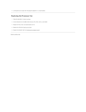
Lift the processor fan away from the computer and place it in Before You Begin. 2. Replace the computer cover (see Replacing the Shield). 5. Replace the shield (see Replacing the Computer Cover). Connect the processor fan cable to Contents Page Back to the connector (CPU_FAN1) on the system board. 3. Replacing the Processor Fan 1. Replace the three screws securing the processor fan. 4. Follow the procedures in a secure location. 6.
Lift the processor fan away from the computer and place it in Before You Begin. 2. Replace the computer cover (see Replacing the Shield). 5. Replace the shield (see Replacing the Computer Cover). Connect the processor fan cable to Contents Page Back to the connector (CPU_FAN1) on the system board. 3. Replacing the Processor Fan 1. Replace the three screws securing the processor fan. 4. Follow the procedures in a secure location. 6.

Service Manual
Page 20
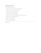
...cable from the inverter. 11. Remove the back I /O Panel). 6. Remove the processor fan and heat sink (see Removing the Back I /O panel (see Removing the Heat Sink and Removing the Processor Fan). 7. Disconnect the two cables that secure the inverter to the LCD panel. 12. Remove... the right speaker (see the Regulatory Compliance Homepage at www.dell.com/regulatory_compliance. Lift the inverter out of the chassis. 1 screws (2) 3 inverter cable 2 cables to Contents Page Inverter Dell Studio One 19/...
...cable from the inverter. 11. Remove the back I /O Panel). 6. Remove the processor fan and heat sink (see Removing the Back I /O panel (see Removing the Heat Sink and Removing the Processor Fan). 7. Disconnect the two cables that secure the inverter to the LCD panel. 12. Remove... the right speaker (see the Regulatory Compliance Homepage at www.dell.com/regulatory_compliance. Lift the inverter out of the chassis. 1 screws (2) 3 inverter cable 2 cables to Contents Page Inverter Dell Studio One 19/...
Service Manual
Page 21
... Replacing the Right Speaker). 7. Replacing the Inverter 1. To replace the inverter, connect the two cables from the LCD panel to the chassis. 5. Replace the processor fan and heat sink (see Replacing the Stand). 10. Replace the stand (see Replacing the Heat Sink and Replacing the Processor...
... Replacing the Right Speaker). 7. Replacing the Inverter 1. To replace the inverter, connect the two cables from the LCD panel to the chassis. 5. Replace the processor fan and heat sink (see Replacing the Stand). 10. Replace the stand (see Replacing the Heat Sink and Replacing the Processor...

Service Manual
Page 30
... Do not perform the following steps unless you are familiar with your computer. Remove the computer cover (see the Regulatory Compliance Homepage at www.dell.com/regulatory_compliance. Remove the stand (see Removing the Shield). 4. Removing the Power Supply Unit 1. Back to the chassis. 1 power supply... assistance, see the Setup Guide. Remove the four screws that secure the power supply unit to Contents Page Power Supply Unit Dell Studio One 19/1909 Service Manual Removing the Power Supply Unit Replacing the Power Supply Unit WARNING: Before working inside your computer, read the ...
... Do not perform the following steps unless you are familiar with your computer. Remove the computer cover (see the Regulatory Compliance Homepage at www.dell.com/regulatory_compliance. Remove the stand (see Removing the Shield). 4. Removing the Power Supply Unit 1. Back to the chassis. 1 power supply... assistance, see the Setup Guide. Remove the four screws that secure the power supply unit to Contents Page Power Supply Unit Dell Studio One 19/1909 Service Manual Removing the Power Supply Unit Replacing the Power Supply Unit WARNING: Before working inside your computer, read the ...

Service Manual
Page 35
...fan and heat sink (see the Regulatory Compliance Homepage at www.dell.com/regulatory_compliance. Follow the procedures in Before You Begin. 2. Removing the Right Speaker NOTE: To locate the right speaker, see Removing the Stand). 5. Remove the four screws that secure the speaker to Contents Page Speakers Dell Studio One 19... Removing the Heat Sink and Removing the Processor Fan). 6. Remove the shield (see Removing the Computer Cover). 3. Disconnect the right speaker cable from the chassis. NOTE: Make a note of Your Studio One. 1. Remove the computer cover (see Removing ...
...fan and heat sink (see the Regulatory Compliance Homepage at www.dell.com/regulatory_compliance. Follow the procedures in Before You Begin. 2. Removing the Right Speaker NOTE: To locate the right speaker, see Removing the Stand). 5. Remove the four screws that secure the speaker to Contents Page Speakers Dell Studio One 19... Removing the Heat Sink and Removing the Processor Fan). 6. Remove the shield (see Removing the Computer Cover). 3. Disconnect the right speaker cable from the chassis. NOTE: Make a note of Your Studio One. 1. Remove the computer cover (see Removing ...

Service Manual
Page 36
2. Follow the procedures in Before You Begin. 2. NOTE: Make a note of Your Studio One. 1. To replace the speaker, route the speaker cables back into position. Connect the right speaker cable to electrical outlets, and turn them on. ... Replace the shield (see Replacing the Stand). 7. Replace the stand (see Replacing the Shield). 8. Follow the procedures in Before You Begin. 2. Replace the processor fan and heat sink (see Replacing the Computer Cover). 9. Lift the speaker away from the connector (SPEAKER_1) on the system board. 4. Replace the computer cover (see...
2. Follow the procedures in Before You Begin. 2. NOTE: Make a note of Your Studio One. 1. To replace the speaker, route the speaker cables back into position. Connect the right speaker cable to electrical outlets, and turn them on. ... Replace the shield (see Replacing the Stand). 7. Replace the stand (see Replacing the Shield). 8. Follow the procedures in Before You Begin. 2. Replace the processor fan and heat sink (see Replacing the Computer Cover). 9. Lift the speaker away from the connector (SPEAKER_1) on the system board. 4. Replace the computer cover (see...

Service Manual
Page 40
...Tag, which is also visible on a barcode label on the computer. Removing the System Board 1. Remove the stand (see Removing the Processor Fan and Removing the Heat Sink). 7. CAUTION: To avoid electrostatic discharge, ground yourself by using a wrist grounding strap or by their edges, ... the Shield). 4. Back to the chassis. 10. Remove the five screws that secure the system board to Contents Page System Board Dell Studio One 19/1909 Service Manual Removing the System Board Replacing the System Board WARNING: Before working inside your computer, read the safety information that secure...
...Tag, which is also visible on a barcode label on the computer. Removing the System Board 1. Remove the stand (see Removing the Processor Fan and Removing the Heat Sink). 7. CAUTION: To avoid electrostatic discharge, ground yourself by using a wrist grounding strap or by their edges, ... the Shield). 4. Back to the chassis. 10. Remove the five screws that secure the system board to Contents Page System Board Dell Studio One 19/1909 Service Manual Removing the System Board Replacing the System Board WARNING: Before working inside your computer, read the safety information that secure...

Service Manual
Page 41
... system board place the system board back in damage to do so may result in the chassis. 3. Replace the computer cover (see Replacing the System Fan and Heat Sink Assembly). 7. 1 screws (5) 2 M2.5 x 5-mm screws (5) 11. Failure to the computer. 12. Replace the stand (see Replacing the Shield). 11. Follow...10. Turn on the computer. Replace the five M2.5 x 5-mm screws that accompanied the replacement system board into the appropriate drive. Replace the processor fan and heat sink (see Replacing the Back I/O Panel). 9. Replace the back I/O panel (see Replacing the Processor...
... system board place the system board back in damage to do so may result in the chassis. 3. Replace the computer cover (see Replacing the System Fan and Heat Sink Assembly). 7. 1 screws (5) 2 M2.5 x 5-mm screws (5) 11. Failure to the computer. 12. Replace the stand (see Replacing the Shield). 11. Follow...10. Turn on the computer. Replace the five M2.5 x 5-mm screws that accompanied the replacement system board into the appropriate drive. Replace the processor fan and heat sink (see Replacing the Back I/O Panel). 9. Replace the back I/O panel (see Replacing the Processor...

Service Manual
Page 42
... practices information, see Replacing the Stand). 5. Remove the stand (see the Regulatory Compliance Homepage at www.dell.com/regulatory_compliance. Slide and lift the system fan away from the connector (SYS_FAN1) on . CAUTION: Do not perform the following steps unless you touch it...sure that shipped with hardware removal and replacement. Back to Contents Page System Fan and Heat Sink Assembly Dell Studio One 19/1909 Service Manual Removing the System Fan and Heat Sink Assembly Replacing the System Fan and Heat Sink Assembly WARNING: Before working inside your computer, read the...
... practices information, see Replacing the Stand). 5. Remove the stand (see the Regulatory Compliance Homepage at www.dell.com/regulatory_compliance. Slide and lift the system fan away from the connector (SYS_FAN1) on . CAUTION: Do not perform the following steps unless you touch it...sure that shipped with hardware removal and replacement. Back to Contents Page System Fan and Heat Sink Assembly Dell Studio One 19/1909 Service Manual Removing the System Fan and Heat Sink Assembly Replacing the System Fan and Heat Sink Assembly WARNING: Before working inside your computer, read the...

Service Manual
Page 43
... the shield (see Replacing the Stand). 7. Follow the procedures in a secure location. To replace the system fan and heat sink assembly, connect the system fan cable to the system board. 5. Replace the stand (see Replacing the Shield). 8. 1 heat sink captive screws (2)... 3 system fan cable 2 system fan screws (3) 10. Replace the back I /O Panel). 6. Replace the three screws securing the system fan to the connector (SYS_FAN1) on the system board. 3. Replace the computer cover (see Replacing ...
... the shield (see Replacing the Stand). 7. Follow the procedures in a secure location. To replace the system fan and heat sink assembly, connect the system fan cable to the system board. 5. Replace the stand (see Replacing the Shield). 8. 1 heat sink captive screws (2)... 3 system fan cable 2 system fan screws (3) 10. Replace the back I /O Panel). 6. Replace the three screws securing the system fan to the connector (SYS_FAN1) on the system board. 3. Replace the computer cover (see Replacing ...
Service Manual
Page 50
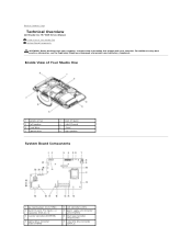
... WARNING: Before working inside your computer, read the safety information that shipped with your computer. Back to Contents Page Technical Overview Dell Studio One 19/1909 Service Manual Inside View of Your Studio One 1 processor fan 3 left speaker 5 hard drive 7 optical drive 2 back I/O panel 4 side I/O panel 6 stand 8 right speaker System Board Components 1 password jumper (CLR_PSWD) ... 6 touch pad connector (TOUCH_PAD) 8 serial ATA drive connector (SATA_2) For additional safety best practices information, see the Regulatory Compliance Homepage at www.dell.com/regulatory_compliance.
... WARNING: Before working inside your computer, read the safety information that shipped with your computer. Back to Contents Page Technical Overview Dell Studio One 19/1909 Service Manual Inside View of Your Studio One 1 processor fan 3 left speaker 5 hard drive 7 optical drive 2 back I/O panel 4 side I/O panel 6 stand 8 right speaker System Board Components 1 password jumper (CLR_PSWD) ... 6 touch pad connector (TOUCH_PAD) 8 serial ATA drive connector (SATA_2) For additional safety best practices information, see the Regulatory Compliance Homepage at www.dell.com/regulatory_compliance.

Service Manual
Page 51
... right speaker connector (SPEAKER_2) 15 memory module connector (SODIMM2) 10 CMOS jumper (CLR_CMOS) 12 processor fan connector (CPU_FAN1) 14 memory module connector (SODIMM1) 16 webcam connector (WEBCAM) 17 digital microphone connector (DIGITAL_MIC) 18 left speaker connector (SPEAKER_1) 19 WLAN connector (WLAN) 20 side I/O panel connector (SIDE_BOARD1) 21 serial ATA drive connector (SATA_1...
... right speaker connector (SPEAKER_2) 15 memory module connector (SODIMM2) 10 CMOS jumper (CLR_CMOS) 12 processor fan connector (CPU_FAN1) 14 memory module connector (SODIMM1) 16 webcam connector (WEBCAM) 17 digital microphone connector (DIGITAL_MIC) 18 left speaker connector (SPEAKER_1) 19 WLAN connector (WLAN) 20 side I/O panel connector (SIDE_BOARD1) 21 serial ATA drive connector (SATA_1...

Setup Guide
Page 14
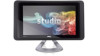
Blocking the vents will cause serious thermal problems. 2 Camera activity light (optional) - Indicates if the camera is normal and does not indicate a problem with the fan or the computer. WARNING: Ensure that none of the computer air vents are turned on or off. 7 5 6 12 Fan noise is on automatically when the computer gets hot. Internal fans create airflow through the vents to prevent the computer from overheating. The fans are blocked. Using Your Studio One Front View Features 1 23 4 1 Air vents -
Blocking the vents will cause serious thermal problems. 2 Camera activity light (optional) - Indicates if the camera is normal and does not indicate a problem with the fan or the computer. WARNING: Ensure that none of the computer air vents are turned on or off. 7 5 6 12 Fan noise is on automatically when the computer gets hot. Internal fans create airflow through the vents to prevent the computer from overheating. The fans are blocked. Using Your Studio One Front View Features 1 23 4 1 Air vents -


