
Service Manual
Page 1
... than its own. Model: DCMA July 2008 Rev. Dell Inc. Reproduction of Dell Inc.; A00 Information in this text: Dell, the DELL logo, and Dell Studio are either potential damage to hardware or loss of your computer. Dell Studio™ 540 Service Manual Technical Overview Before You Begin Replacing the Computer... use of data and tells you how to avoid the problem. NOTICE: A NOTICE indicates either trademarks or registered trademarks of Dell Inc. Trademarks used in this document is strictly forbidden. Other trademarks and trade names may be used in this document to ...
... than its own. Model: DCMA July 2008 Rev. Dell Inc. Reproduction of Dell Inc.; A00 Information in this text: Dell, the DELL logo, and Dell Studio are either potential damage to hardware or loss of your computer. Dell Studio™ 540 Service Manual Technical Overview Before You Begin Replacing the Computer... use of data and tells you how to avoid the problem. NOTICE: A NOTICE indicates either trademarks or registered trademarks of Dell Inc. Trademarks used in this document is strictly forbidden. Other trademarks and trade names may be used in this document to ...

Service Manual
Page 2
... before you begin working inside the computer. 1. Shut down your computer. Back to Contents Page Before You Begin Dell Studio™ 540 Service Manual Technical Specifications Recommended Tools Turning Off Your Computer Safety Instructions This chapter provides procedures for about 4 seconds to...each procedure assumes that the following safety guidelines to help to ensure your computer (see the Regulatory Compliance Homepage at support.dell.com. l You have read the safety information that shipped with your computer. Technical Specifications For information on your computer....
... before you begin working inside the computer. 1. Shut down your computer. Back to Contents Page Before You Begin Dell Studio™ 540 Service Manual Technical Specifications Recommended Tools Turning Off Your Computer Safety Instructions This chapter provides procedures for about 4 seconds to...each procedure assumes that the following safety guidelines to help to ensure your computer (see the Regulatory Compliance Homepage at support.dell.com. l You have read the safety information that shipped with your computer. Technical Specifications For information on your computer....
Service Manual
Page 4
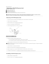
...Card. Replace the card retention bracket. Remove the computer cover. For more information, see the Regulatory Compliance Homepage at www.dell.com/regulatory_compliance. Replace the computer cover, reconnect the computer and devices to the card. Follow the procedures in the empty card... To complete the removal procedure, see Replacing the Computer Cover). 4. Back to Contents Page Replacing a PCI/PCI Express Card Dell Studio™ 540 Service Manual Removing a PCI/PCI Express Card Installing a PCI/PCI Express Card Replacing the Card Retention Bracket Configuring Your Computer ...
...Card. Replace the card retention bracket. Remove the computer cover. For more information, see the Regulatory Compliance Homepage at www.dell.com/regulatory_compliance. Replace the computer cover, reconnect the computer and devices to the card. Follow the procedures in the empty card... To complete the removal procedure, see Replacing the Computer Cover). 4. Back to Contents Page Replacing a PCI/PCI Express Card Dell Studio™ 540 Service Manual Removing a PCI/PCI Express Card Installing a PCI/PCI Express Card Replacing the Card Retention Bracket Configuring Your Computer ...

Service Manual
Page 7
... additional safety best practices information, see System Board Components). Locate the battery socket (see the Regulatory Compliance Homepage at www.dell.com/regulatory_compliance. Remove the battery from the battery and the battery will pop out. 6. Replace the computer cover (see ... your computer. Back to Contents Page Follow the procedures in Before You Begin. 3. Back to Contents Page Replacing the Battery Dell Studio™ 540 Service Manual CAUTION: Before working inside your computer, read the safety information that shipped with the same or equivalent type recommended ...
... additional safety best practices information, see System Board Components). Locate the battery socket (see the Regulatory Compliance Homepage at www.dell.com/regulatory_compliance. Remove the battery from the battery and the battery will pop out. 6. Replace the computer cover (see ... your computer. Back to Contents Page Follow the procedures in Before You Begin. 3. Back to Contents Page Replacing the Battery Dell Studio™ 540 Service Manual CAUTION: Before working inside your computer, read the safety information that shipped with the same or equivalent type recommended ...

Service Manual
Page 8
Back to Contents Page Replacing the Computer Cover Dell Studio™ 540 Service Manual CAUTION: Before working inside your computer, read the safety information that sufficient space exists to support the system with the computer cover facing ....) of electric shock, laceration by moving fan blades or other unexpected injuries, always unplug your computer on its side with the cover removed-at www.dell.com/regulatory_compliance. NOTICE: Ensure that shipped with your computer.
Back to Contents Page Replacing the Computer Cover Dell Studio™ 540 Service Manual CAUTION: Before working inside your computer, read the safety information that sufficient space exists to support the system with the computer cover facing ....) of electric shock, laceration by moving fan blades or other unexpected injuries, always unplug your computer on its side with the cover removed-at www.dell.com/regulatory_compliance. NOTICE: Ensure that shipped with your computer.

Service Manual
Page 9
... Replacing the Computer Cover). Lift up the processor to remove it from the tab that secures it . 3. Back to Contents Page Replacing the Processor Dell Studio™ 540 Service Manual CAUTION: Before working inside the socket or allow any objects to touch the underside of the processor. NOTICE: Do not perform the following...
... Replacing the Computer Cover). Lift up the processor to remove it from the tab that secures it . 3. Back to Contents Page Replacing the Processor Dell Studio™ 540 Service Manual CAUTION: Before working inside the socket or allow any objects to touch the underside of the processor. NOTICE: Do not perform the following...

Service Manual
Page 12
..., see Replacing the Computer Cover). 3. Remove the computer cover (see the Regulatory Compliance Homepage at www.dell.com/regulatory_compliance. NOTE: The system does not support IDE devices. Back to Contents Page Replacing Drives Dell Studio™ 540 Service Manual Replacing a Hard Drive Replacing a CD/DVD Drive Replacing the FlexDock Removing the FlexDock Break-Away...
..., see Replacing the Computer Cover). 3. Remove the computer cover (see the Regulatory Compliance Homepage at www.dell.com/regulatory_compliance. NOTE: The system does not support IDE devices. Back to Contents Page Replacing Drives Dell Studio™ 540 Service Manual Replacing a Hard Drive Replacing a CD/DVD Drive Replacing the FlexDock Removing the FlexDock Break-Away...

Service Manual
Page 18
Back to Contents Page Replacing Fans Dell Studio™ 540 Service Manual Replacing the Chassis Fan Replacing the Processor Fan and Heat Sink Assembly CAUTION: Before working inside your computer, read the safety information that ... away from the system board connector (SYS_FAN1). 4. Follow the procedures in Before You Begin. 2. Remove the computer cover (see the Regulatory Compliance Homepage at www.dell.com/regulatory_compliance. This could damage the fan. 1 screws (4) 2 chassis fan 1. Replacing the Chassis Fan NOTICE: Do not touch the fan blades when you are removing...
Back to Contents Page Replacing Fans Dell Studio™ 540 Service Manual Replacing the Chassis Fan Replacing the Processor Fan and Heat Sink Assembly CAUTION: Before working inside your computer, read the safety information that ... away from the system board connector (SYS_FAN1). 4. Follow the procedures in Before You Begin. 2. Remove the computer cover (see the Regulatory Compliance Homepage at www.dell.com/regulatory_compliance. This could damage the fan. 1 screws (4) 2 chassis fan 1. Replacing the Chassis Fan NOTICE: Do not touch the fan blades when you are removing...

Service Manual
Page 20
Grasp and lift the front panel grips one at www.dell.com/regulatory_compliance. 1. To replace the front panel, align and insert the front panel clamps in Before You Begin. 2. Replace the computer cover (see Replacing the ... the front of the computer to release it snaps into place on the front of the computer. 4. Back to Contents Page Replacing the Front Panel Dell Studio™ 540 Service Manual CAUTION: Before working inside your computer, read the safety information that shipped with your computer. Remove the computer cover (see Replacing the...
Grasp and lift the front panel grips one at www.dell.com/regulatory_compliance. 1. To replace the front panel, align and insert the front panel clamps in Before You Begin. 2. Replace the computer cover (see Replacing the ... the front of the computer to release it snaps into place on the front of the computer. 4. Back to Contents Page Replacing the Front Panel Dell Studio™ 540 Service Manual CAUTION: Before working inside your computer, read the safety information that shipped with your computer. Remove the computer cover (see Replacing the...

Service Manual
Page 21
..., and turn them on. Replace the front panel (see Replacing the Computer Cover). 3. Back to computer problems. 5. Remove the screw that secures the I /O Panel Dell Studio™ 540 Service Manual CAUTION: Before working inside your computer, read the safety information that secures the I /O panel 8. Remove the computer cover (see Replacing the Front Panel...
..., and turn them on. Replace the front panel (see Replacing the Computer Cover). 3. Back to computer problems. 5. Remove the screw that secures the I /O Panel Dell Studio™ 540 Service Manual CAUTION: Before working inside your computer, read the safety information that secures the I /O panel 8. Remove the computer cover (see Replacing the Front Panel...

Service Manual
Page 22
...upwards. If the module is difficult to remove, gently ease the module back and forth to Contents Page Replacing Memory Module(s) Dell Studio™ 540 Service Manual CAUTION: Before working inside your computer. For additional safety best practices information, see the Regulatory Compliance Homepage at ...computer, read the safety information that you install a single memory module in Before You Begin. 2. Press out the securing clip at www.dell.com/regulatory_compliance. 1. If possible, do not pair an original memory module with the tab on the bottom of the slowest module installed....
...upwards. If the module is difficult to remove, gently ease the module back and forth to Contents Page Replacing Memory Module(s) Dell Studio™ 540 Service Manual CAUTION: Before working inside your computer. For additional safety best practices information, see the Regulatory Compliance Homepage at ...computer, read the safety information that you install a single memory module in Before You Begin. 2. Press out the securing clip at www.dell.com/regulatory_compliance. 1. If possible, do not pair an original memory module with the tab on the bottom of the slowest module installed....
Service Manual
Page 24
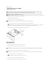
... cause electrical shock as you remove them on. NOTE: Double-check all screws that secure the power supply to Contents Page Replacing the Power Supply Dell Studio™ 540 Service Manual CAUTION: Before working inside your computer from being pinched or crimped. 4. CAUTION: To guard against likelihood of electric shock, laceration by moving...
... cause electrical shock as you remove them on. NOTE: Double-check all screws that secure the power supply to Contents Page Replacing the Power Supply Dell Studio™ 540 Service Manual CAUTION: Before working inside your computer from being pinched or crimped. 4. CAUTION: To guard against likelihood of electric shock, laceration by moving...

Service Manual
Page 26
... the rubber foot to secure the rubber foot to the chassis. 1 rubber foot pin 3 rubber foot slot Back to Contents Page Replacing the Rubber Foot Dell Studio™ 540 Service Manual CAUTION: Before working inside your computer, read the safety information that shipped with your computer. Back to Contents Page 2 rubber foot For...
... the rubber foot to secure the rubber foot to the chassis. 1 rubber foot pin 3 rubber foot slot Back to Contents Page Replacing the Rubber Foot Dell Studio™ 540 Service Manual CAUTION: Before working inside your computer, read the safety information that shipped with your computer. Back to Contents Page 2 rubber foot For...

Service Manual
Page 27
Back to Contents Page Replacing the System Board Dell Studio™ 540 Service Manual CAUTION: Before working inside your computer, read the safety information that shipped with hardware removal and replacement. Be sure that you .... 7. Remove the processor (see the Setup Guide. 1. For technical assistance, see Replacing the Processor). 6. Replace the cables that you are preset at www.dell.com/regulatory_compliance. Remove the computer cover (see Replacing the Processor). Remove the memory modules (see the Regulatory Compliance Homepage at the factory. 10. CAUTION: The...
Back to Contents Page Replacing the System Board Dell Studio™ 540 Service Manual CAUTION: Before working inside your computer, read the safety information that shipped with hardware removal and replacement. Be sure that you .... 7. Remove the processor (see the Setup Guide. 1. For technical assistance, see Replacing the Processor). 6. Replace the cables that you are preset at www.dell.com/regulatory_compliance. Remove the computer cover (see Replacing the Processor). Remove the memory modules (see the Regulatory Compliance Homepage at the factory. 10. CAUTION: The...

Service Manual
Page 29
Back to Contents Page System Setup Dell Studio™ 540 Service Manual Overview Clearing Forgotten Passwords Clearing ... and down the system setup screen information for your computer (see the Microsoft® Windows® desktop. Appears on your computer, including installed hardware, power conservation, and security features. NOTE: Not all...Then, shut down -arrow keys. Options Field - Press andkeys to the System Setup options. When the blue DELL™ logo is divided into three areas: the options list, active options field, and key functions. Options ...
Back to Contents Page System Setup Dell Studio™ 540 Service Manual Overview Clearing Forgotten Passwords Clearing ... and down the system setup screen information for your computer (see the Microsoft® Windows® desktop. Appears on your computer, including installed hardware, power conservation, and security features. NOTE: Not all...Then, shut down -arrow keys. Options Field - Press andkeys to the System Setup options. When the blue DELL™ logo is divided into three areas: the options list, active options field, and key functions. Options ...

Service Manual
Page 34
For additional safety best practices information, see the Regulatory Compliance Homepage at www.dell.com/regulatory_compliance. Inside View of Your Computer System Board Components CAUTION: Before working inside your computer, read the safety information that shipped with your computer. Back to Contents Page Technical Overview Dell Studio™ 540 Service Manual Inside View of Your Computer 1 optional hard drive 3 FlexDock 5 power supply 2 hard drive 4 optional CD or DVD drive 6 CD or DVD drive System Board Components 1 processor socket (CPU) 2 processor fan connector
For additional safety best practices information, see the Regulatory Compliance Homepage at www.dell.com/regulatory_compliance. Inside View of Your Computer System Board Components CAUTION: Before working inside your computer, read the safety information that shipped with your computer. Back to Contents Page Technical Overview Dell Studio™ 540 Service Manual Inside View of Your Computer 1 optional hard drive 3 FlexDock 5 power supply 2 hard drive 4 optional CD or DVD drive 6 CD or DVD drive System Board Components 1 processor socket (CPU) 2 processor fan connector

Service Manual
Page 36
... either trademarks or registered trademarks of Dell Inc.; All rights reserved. CAUTION: A CAUTION indicates a potential for property damage, personal injury, or death. Other trademarks and trade names may be used in this text: Dell, the DELL logo, and Dell Studio are either the entities claiming the ...marks and names or their products. Dell Inc. July 2008 Rev. A00 Back to hardware or loss of your computer. Back to Contents Page Dell Studio™ 540 Service Manual NOTE: A NOTE...
... either trademarks or registered trademarks of Dell Inc.; All rights reserved. CAUTION: A CAUTION indicates a potential for property damage, personal injury, or death. Other trademarks and trade names may be used in this text: Dell, the DELL logo, and Dell Studio are either the entities claiming the ...marks and names or their products. Dell Inc. July 2008 Rev. A00 Back to hardware or loss of your computer. Back to Contents Page Dell Studio™ 540 Service Manual NOTE: A NOTE...
Setup Guide
Page 5
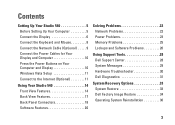
... the Power Buttons on Your Computer and Display 10 Windows Vista Setup 11 Connect to the Internet (Optional 11 Using Your Studio 540 14 Front View Features 14 Back View Features 17 Back Panel Connectors 18 Software Features 20 Solving Problems 22 Network Problems 22... Power Problems 23 Memory Problems 25 Lockups and Software Problems 26 Using Support Tools 28 Dell Support Center 28 System Messages 29 Hardware Troubleshooter 30 Dell Diagnostics 31 System Recovery Options 33 System Restore 33 Dell Factory Image Restore 34 Operating System Reinstallation 36 3
... the Power Buttons on Your Computer and Display 10 Windows Vista Setup 11 Connect to the Internet (Optional 11 Using Your Studio 540 14 Front View Features 14 Back View Features 17 Back Panel Connectors 18 Software Features 20 Solving Problems 22 Network Problems 22... Power Problems 23 Memory Problems 25 Lockups and Software Problems 26 Using Support Tools 28 Dell Support Center 28 System Messages 29 Hardware Troubleshooter 30 Dell Diagnostics 31 System Recovery Options 33 System Restore 33 Dell Factory Image Restore 34 Operating System Reinstallation 36 3

Setup Guide
Page 7
You should never place your Studio 540 may cause it is powered on all other sides. To prevent overheating ensure that you leave at least 10.2 cm (4 inches) at the back of ... an enclosed space, such as a cabinet or drawer when it to place your computer. Before Setting Up Your Computer When positioning your Studio 540 and connecting peripherals. Setting Up Your Studio 540 This section provides information about setting up your computer, ensure that you allow easy access to a power source, adequate ventilation, and a level...
You should never place your Studio 540 may cause it is powered on all other sides. To prevent overheating ensure that you leave at least 10.2 cm (4 inches) at the back of ... an enclosed space, such as a cabinet or drawer when it to place your computer. Before Setting Up Your Computer When positioning your Studio 540 and connecting peripherals. Setting Up Your Studio 540 This section provides information about setting up your computer, ensure that you allow easy access to a power source, adequate ventilation, and a level...

Setup Guide
Page 8
Setting Up Your Studio 540 Connect the Display Your computer uses one of two different connectors for displays such as monitors and projectors. -OR- NOTE: A DVI connector may be available on your computer if you purchased an optional discreet graphics card. 6 The HDMI connector is a high-performance digital connector that carries both video and audio signals for connecting the display. The VGA connector carries only video signals for displays such as TVs and monitors with integrated speakers.
Setting Up Your Studio 540 Connect the Display Your computer uses one of two different connectors for displays such as monitors and projectors. -OR- NOTE: A DVI connector may be available on your computer if you purchased an optional discreet graphics card. 6 The HDMI connector is a high-performance digital connector that carries both video and audio signals for connecting the display. The VGA connector carries only video signals for displays such as TVs and monitors with integrated speakers.

