
Dell Networking Getting Started Guide
Page 5
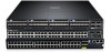
.... The S5000 supports Data Center Bridging (ETS/PFC/DCBX), FCoE Transit (FIP Snooping), NPIV Proxy Gateway (NPG), and Internet small computer system interface (iSCSI) storage traffic. The S5000 delivers Fibre Channel over Ethernet (FCoE) and Fibre Channel (FC) capability in the same box. Product Description The S5000 is part of Dell Networking's S-Series switches for...
.... The S5000 supports Data Center Bridging (ETS/PFC/DCBX), FCoE Transit (FIP Snooping), NPIV Proxy Gateway (NPG), and Internet small computer system interface (iSCSI) storage traffic. The S5000 delivers Fibre Channel over Ethernet (FCoE) and Fibre Channel (FC) capability in the same box. Product Description The S5000 is part of Dell Networking's S-Series switches for...
Dell Networking Getting Started Guide
Page 6
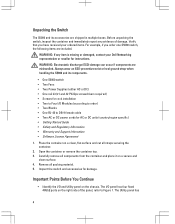
... License Agreement 1. The Utility panel has 4 Before unpacking the switch, inspect the container and immediately report any item is missing or damaged, contact your ordered items. For example, if you order one S5000 switch, the following items are included. Always wear an ESD-preventive ...wrist or heel ground strap when handling the S5000 and its accessories are mishandled. Verify that you have received your Dell Networking representative or reseller for instructions. Place...
... License Agreement 1. The Utility panel has 4 Before unpacking the switch, inspect the container and immediately report any item is missing or damaged, contact your ordered items. For example, if you order one S5000 switch, the following items are included. Always wear an ESD-preventive ...wrist or heel ground strap when handling the S5000 and its accessories are mishandled. Verify that you have received your Dell Networking representative or reseller for instructions. Place...
Dell Networking Getting Started Guide
Page 8
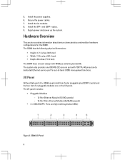
... QSFP+ Ports and light emitting diodes (LEDs) Figure 2. The system also provides one DB9 RS-232 console port with 640Gbps switching bandwidth. The I /O Panel 6 5. Install the SFP+ and QSFP+ optics. 9. The S5000 has the following physical dimensions: • Height: 1.71 inches (43.5 mm) • Width: 17.4 inches (441.9 mm) • Depth: 28...
... QSFP+ Ports and light emitting diodes (LEDs) Figure 2. The system also provides one DB9 RS-232 console port with 640Gbps switching bandwidth. The I /O Panel 6 5. Install the SFP+ and QSFP+ optics. 9. The S5000 has the following physical dimensions: • Height: 1.71 inches (43.5 mm) • Width: 17.4 inches (441.9 mm) • Depth: 28...

Dell Networking Getting Started Guide
Page 9
... and power modules. Slot 3 (for Fan Module 0) 3. Slot 1 (for PSU 1) 5. S5000 Power Supplies and Fan Modules 1. Figure 3. Grab Handles Power Supplies The S5000 supports two hot-swappable PSUs. To ensure power redundancy and adequate cooling, install two power supplies in the switch. NOTE: The PSUs must be installed at the customer site. Slot...
... and power modules. Slot 3 (for Fan Module 0) 3. Slot 1 (for PSU 1) 5. S5000 Power Supplies and Fan Modules 1. Figure 3. Grab Handles Power Supplies The S5000 supports two hot-swappable PSUs. To ensure power redundancy and adequate cooling, install two power supplies in the switch. NOTE: The PSUs must be installed at the customer site. Slot...

Dell Networking Getting Started Guide
Page 11
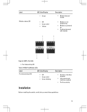
... LED 7. Figure 5. System status LED 4. Seven-segment display to the FTOS Command Line Reference Guide and FTOS Configuration Guide for the S5000 system. Locator beacon LED 2. Fan status LED NOTE: For AC PSUs, an illuminated translucent handle indicates the power status. • ...Management: Port 0 System Status You can view S5000 status information in the following table lists the LED definitions for the S5000 Switch. For more information about these options, refer to identify Stack ID 6. NOTE: For DC PSUs...
... LED 7. Figure 5. System status LED 4. Seven-segment display to the FTOS Command Line Reference Guide and FTOS Configuration Guide for the S5000 system. Locator beacon LED 2. Fan status LED NOTE: For AC PSUs, an illuminated translucent handle indicates the power status. • ...Management: Port 0 System Status You can view S5000 status information in the following table lists the LED definitions for the S5000 Switch. For more information about these options, refer to identify Stack ID 6. NOTE: For DC PSUs...

Dell Networking Getting Started Guide
Page 12
... alarm • Critical alarm • No power • Normal operation • System is booting • System in card problem state • Switch in Stacking Master mode OR Switch in Standalone mode • Switch in Stacking Standby mode 10 Alarm LED 3. System status LED Table 2. System LED Displays (Utility and I /O Panel) 1. Locator beacon LED...
... alarm • Critical alarm • No power • Normal operation • System is booting • System in card problem state • Switch in Stacking Master mode OR Switch in Standalone mode • Switch in Stacking Standby mode 10 Alarm LED 3. System status LED Table 2. System LED Displays (Utility and I /O Panel) 1. Locator beacon LED...

Dell Networking Getting Started Guide
Page 13
Port locator beacon LED 2. Label PSU status LED Fan status LED LED Color/Display • Green solid • Off • Green solid • Off Description • Switch in Stacking Member mode • Normal operation • Power not present • Normal operation • Power not present Figure 7. Module locator beacon LED 4. Port link/activity LED 3. Module LEDs 1. Module status LED NOTE: The downward and upward pointing triangles denote the lower and upper port LEDs respectively. 11
Port locator beacon LED 2. Label PSU status LED Fan status LED LED Color/Display • Green solid • Off • Green solid • Off Description • Switch in Stacking Member mode • Normal operation • Power not present • Normal operation • Power not present Figure 7. Module locator beacon LED 4. Port link/activity LED 3. Module LEDs 1. Module status LED NOTE: The downward and upward pointing triangles denote the lower and upper port LEDs respectively. 11
Dell Networking Getting Started Guide
Page 15
... solid • Green blinking Description • No link or interface disabled • Link present and interface enabled • Port has activity Installation Before installing the switch, verify that you meet these guidelines: 13 Label Module status LED LED Color/Display • Green • Off • Green solid • Yellow Description •...
... solid • Green blinking Description • No link or interface disabled • Link present and interface enabled • Port has activity Installation Before installing the switch, verify that you meet these guidelines: 13 Label Module status LED LED Color/Display • Green • Off • Green solid • Yellow Description •...
Dell Networking Getting Started Guide
Page 16
... sources of electrical noise, such as fans and blowers in the switch, can draw dust and other particles causing contaminant buildup inside the chassis, which can result in system malfunction. Install the S5000 Chassis in a Rack or Cabinet To install the S5000 system, Dell Networking recommends completing the installation procedures in a closed or multirack...
... sources of electrical noise, such as fans and blowers in the switch, can draw dust and other particles causing contaminant buildup inside the chassis, which can result in system malfunction. Install the S5000 Chassis in a Rack or Cabinet To install the S5000 system, Dell Networking recommends completing the installation procedures in a closed or multirack...

Dell Networking Getting Started Guide
Page 17
... installation. Mount the components beginning at the bottom of their packaging. 2. Do not exceed your rack load rating. 15 Attaching the Mounting Brackets The S5000 is shipped with the chassis. 1. Slide the mounting brackets, as shown in shelf or rack failure, which may damage equipment and cause possible personal ...out of the rack, then work to the top. Overloading or uneven loading of the chassis 2. Utility side of racks may either place the switch on the rack shelf or mount the switch directly into a 19" wide, EIA-310-E- Figure 9. compliant rack. • Rack loading -
... installation. Mount the components beginning at the bottom of their packaging. 2. Do not exceed your rack load rating. 15 Attaching the Mounting Brackets The S5000 is shipped with the chassis. 1. Slide the mounting brackets, as shown in shelf or rack failure, which may damage equipment and cause possible personal ...out of the rack, then work to the top. Overloading or uneven loading of the chassis 2. Utility side of racks may either place the switch on the rack shelf or mount the switch directly into a 19" wide, EIA-310-E- Figure 9. compliant rack. • Rack loading -

Dell Networking Getting Started Guide
Page 18
...and to the supply connections other than the room ambient temperature. WARNING: These instructions are tightened firmly. 16 Maintain reliable earthing of the switch. • Reduced air flow - Pay particular attention to avoid hot air blow out from I/O panel. • Reliable earthing - Read...ears" to the power source specified on the unit. Ensure the screws are a condensed reference. Installing the S5000 Chassis into a 4-Post Rack or Cabinet NOTE: Dell Networking recommends that the amount of airflow required for each bracket. Connect only to the rack or cabinet posts,...
...and to the supply connections other than the room ambient temperature. WARNING: These instructions are tightened firmly. 16 Maintain reliable earthing of the switch. • Reduced air flow - Pay particular attention to avoid hot air blow out from I/O panel. • Reliable earthing - Read...ears" to the power source specified on the unit. Ensure the screws are a condensed reference. Installing the S5000 Chassis into a 4-Post Rack or Cabinet NOTE: Dell Networking recommends that the amount of airflow required for each bracket. Connect only to the rack or cabinet posts,...

Dell Networking Getting Started Guide
Page 21
NOTE: A blue color release latch indicates that the Ethernet module supports hot swapping during switch operations. Port Number 19 A red color release latch indicates that the Ethernet module does not support hot swapping during switch operations. Figure 11. Part Name 2. Part name and Port number on the Ethernet Module Handle 1. Instead, you must power down the switch before removing and replacing an Ethernet module.
NOTE: A blue color release latch indicates that the Ethernet module supports hot swapping during switch operations. Port Number 19 A red color release latch indicates that the Ethernet module does not support hot swapping during switch operations. Figure 11. Part Name 2. Part name and Port number on the Ethernet Module Handle 1. Instead, you must power down the switch before removing and replacing an Ethernet module.
Dell Networking Getting Started Guide
Page 22
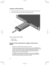
...powered up . Ethernet Module Important Points to slide it . Installing an Ethernet Module 1. Figure 12. If you install or replace it into the switch module slot. 2. Use the grab handle on the Ethernet module to Remember for Installing a Fibre Channel Module • You must insert the ...Fibre Channel module only in a catastrophic failure. • The S5000 does not support the hot swapping of Fibre Channel modules must power down the system before removing and replacing a Fibre Channel module. 20 If...
...powered up . Ethernet Module Important Points to slide it . Installing an Ethernet Module 1. Figure 12. If you install or replace it into the switch module slot. 2. Use the grab handle on the Ethernet module to Remember for Installing a Fibre Channel Module • You must insert the ...Fibre Channel module only in a catastrophic failure. • The S5000 does not support the hot swapping of Fibre Channel modules must power down the system before removing and replacing a Fibre Channel module. 20 If...
Dell Networking Getting Started Guide
Page 24
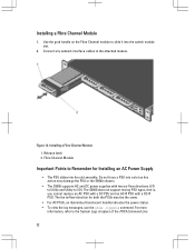
... view the log messages, use the show logging command. Do not force a PSU into a slot as this action may damage the PSU or the S5000 chassis. • The S5000 supports AC and DC power supplies with a DC-R PSU. Installing a Fibre Channel Module 1. Connect any network interface cables to the System Logs chapters...smoothly. For more information, refer to the attached module. The fan airflow direction for Installing an AC Power Supply • The PSU slides into the switch module slot. 2. Installing a Fibre Channel Module 1. Use the grab handle on the Fibre Channel module to I/O).
... view the log messages, use the show logging command. Do not force a PSU into a slot as this action may damage the PSU or the S5000 chassis. • The S5000 supports AC and DC power supplies with a DC-R PSU. Installing a Fibre Channel Module 1. Connect any network interface cables to the System Logs chapters...smoothly. For more information, refer to the attached module. The fan airflow direction for Installing an AC Power Supply • The PSU slides into the switch module slot. 2. Installing a Fibre Channel Module 1. Use the grab handle on the Fibre Channel module to I/O).

Dell Networking Getting Started Guide
Page 25
...same airflow direction (I /O. WARNING: The PCB edge connector is expelled from the electro-static bag. 2. Avoid installing the switch upside down : 00:02:19: %S5000:0 %CHMGR-2-PSU_TYPE_AIRFLOW_MISMATCH: Mismatching PSU airflow detected. The airflow directions are mishandled. Use the grab handle to 3. Always wear an... components. If you install the PSU correctly, it snaps into the switch PSU slot (install the PSU- Remove the PSU from the I /O to Utility or Utility to run on one PSU, Dell Networking highly recommends using two PSUs for a time, be fully inserted...
...same airflow direction (I /O. WARNING: The PCB edge connector is expelled from the electro-static bag. 2. Avoid installing the switch upside down : 00:02:19: %S5000:0 %CHMGR-2-PSU_TYPE_AIRFLOW_MISMATCH: Mismatching PSU airflow detected. The airflow directions are mishandled. Use the grab handle to 3. Always wear an... components. If you install the PSU correctly, it snaps into the switch PSU slot (install the PSU- Remove the PSU from the I /O to Utility or Utility to run on one PSU, Dell Networking highly recommends using two PSUs for a time, be fully inserted...

Dell Networking Getting Started Guide
Page 26
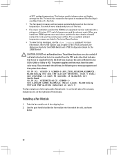
Installing an AC Power Supply 1. Slot 0 (for AC PSU 0) 2. Figure 15. Plug in the AC3 prong cord from the switch PSU to the external power source (the AC wall outlet). 24 Release latch 3.
Installing an AC Power Supply 1. Slot 0 (for AC PSU 0) 2. Figure 15. Plug in the AC3 prong cord from the switch PSU to the external power source (the AC wall outlet). 24 Release latch 3.

Dell Networking Getting Started Guide
Page 29
...I/O). WARNING: The PCB edge connector is , you cannot replace an AC PSU with a DC PSU and an AC-R PSU with only one PSU, Dell Networking highly recommends using DC power supply, peel off the DC electrical label and place it on the main regulatory label found on one PSU... washer 5. #6-32 nut Important Points to run on the bottom of the switch. If the switch needs to Remember for a time, be properly grounded. Position this action may damage the PSU or the S5000 chassis. • The S5000 supports AC and DC power supplies with a blank plate to avoid overheating. Grounding...
...I/O). WARNING: The PCB edge connector is , you cannot replace an AC PSU with a DC PSU and an AC-R PSU with only one PSU, Dell Networking highly recommends using DC power supply, peel off the DC electrical label and place it on the main regulatory label found on one PSU... washer 5. #6-32 nut Important Points to run on the bottom of the switch. If the switch needs to Remember for a time, be properly grounded. Position this action may damage the PSU or the S5000 chassis. • The S5000 supports AC and DC power supplies with a blank plate to avoid overheating. Grounding...

Dell Networking Getting Started Guide
Page 30
...-static bag. 2. Use the grab handle to I /O to Utility or Utility to slide the PSU into place and is flush with the back of the switch. Installing a DC Power Supply 1. Slot 0 (for DC PSU 0) 28 The power supplies and fans must use the same airflow direction (I /O). Unit 0 ...airflow detected in only one way. When you mismatch the airflows, the following error message appears and the system shuts down: 00:02:19: %S5000:0 %CHMGR-2-PSU_TYPE_AIRFLOW_MISMATCH: Mismatching PSU airflow detected. Remove the PSU from the PSU and a blue label indicates that hot air is keyed so that...
...-static bag. 2. Use the grab handle to I /O to Utility or Utility to slide the PSU into place and is flush with the back of the switch. Installing a DC Power Supply 1. Slot 0 (for DC PSU 0) 28 The power supplies and fans must use the same airflow direction (I /O). Unit 0 ...airflow detected in only one way. When you mismatch the airflows, the following error message appears and the system shuts down: 00:02:19: %S5000:0 %CHMGR-2-PSU_TYPE_AIRFLOW_MISMATCH: Mismatching PSU airflow detected. Remove the PSU from the PSU and a blue label indicates that hot air is keyed so that...
Dell Networking Getting Started Guide
Page 34
... two chassis at 26°C ambient temperature. Take the fan module out of the FTOS Command Line Reference Guide for the S5000 Switch and FTOS Configuration Guide for the S5000 Switch. at least 5 inches (12.7 cm) apart to permit proper airflow. For more information, refer to I /O. Unit...: Mismatching PSU and FAN airflow detected. Both fans must have the same color strap. The switch never intentionally turns off the fans. • For proper ventilation, position the S5000 in unit 0 The fan modules are field replaceable. A red label indicates that hot air ...
... two chassis at 26°C ambient temperature. Take the fan module out of the FTOS Command Line Reference Guide for the S5000 Switch and FTOS Configuration Guide for the S5000 Switch. at least 5 inches (12.7 cm) apart to permit proper airflow. For more information, refer to I /O. Unit...: Mismatching PSU and FAN airflow detected. Both fans must have the same color strap. The switch never intentionally turns off the fans. • For proper ventilation, position the S5000 in unit 0 The fan modules are field replaceable. A red label indicates that hot air ...

Dell Networking Getting Started Guide
Page 37
... slows as the cable is connected between the S5000 and the power source, the chassis is powered-up an AC PSU, an AC power cable is powered up ; Dell Networking recommends reinspecting your system prior to powering up , the fans come on /off switch. 35 The AC power connector must order all...the boot-up is complete, the power status LED is sufficient airflow around the unit (which may be on /off switch. Supplying Power and Powering Up the System Supply power to the S5000 system after the chassis is powered-up , the system does not recognize the module. Verify that: • The ...
... slows as the cable is connected between the S5000 and the power source, the chassis is powered-up an AC PSU, an AC power cable is powered up ; Dell Networking recommends reinspecting your system prior to powering up , the fans come on /off switch. 35 The AC power connector must order all...the boot-up is complete, the power status LED is sufficient airflow around the unit (which may be on /off switch. Supplying Power and Powering Up the System Supply power to the S5000 system after the chassis is powered-up , the system does not recognize the module. Verify that: • The ...


