
User's Guide
Page 8
Connect the power cable. *Headphone usage is not supported for the audio line out connector. Side View Bottom View Bottom view without monitor stand Label Description 1 Audio Line-out 2 HDMI connector 3 VGA connector 4 DC power cord connector Use Connect your speakers.* Connect your computer VGA cable. Connect your computer HDMI cable.
Connect the power cable. *Headphone usage is not supported for the audio line out connector. Side View Bottom View Bottom view without monitor stand Label Description 1 Audio Line-out 2 HDMI connector 3 VGA connector 4 DC power cord connector Use Connect your speakers.* Connect your computer VGA cable. Connect your computer HDMI cable.
User's Guide
Page 10
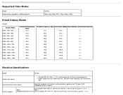
Supported Video Modes Model Video display capabilities (HDMI playback) S2440L 480p, 480i, 576p, 576i, 720p, 1080p, 1080i Preset Display Modes S2440L Display Mode VESA, 720 x 400 VESA, 640 x 480 VESA, 640 x 480 VESA, 800 x 600 VESA, 800 x 600....0 108.0 +/+ 80.0 75.0 135.0 +/+ 67.5 60.0 148.5 +/+ Electrical Specifications Model Video input signals S2440L Analog RGB, 0.7 Volts +/- 5%, positive polarity at 75 ohm input impedance HDMI, 600mV for each differential line, 100 ohm input impedance per differential pair Synchronization input signals Separate horizontal and vertical ...
Supported Video Modes Model Video display capabilities (HDMI playback) S2440L 480p, 480i, 576p, 576i, 720p, 1080p, 1080i Preset Display Modes S2440L Display Mode VESA, 720 x 400 VESA, 640 x 480 VESA, 640 x 480 VESA, 800 x 600 VESA, 800 x 600....0 108.0 +/+ 80.0 75.0 135.0 +/+ 67.5 60.0 148.5 +/+ Electrical Specifications Model Video input signals S2440L Analog RGB, 0.7 Volts +/- 5%, positive polarity at 75 ohm input impedance HDMI, 600mV for each differential line, 100 ohm input impedance per differential pair Synchronization input signals Separate horizontal and vertical ...
User's Guide
Page 11
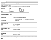
Manufacturer Delta Model ADP-40DD BA Polarity Lite-On PA-1041-71TP-LF Physical Characteristics Model Connector type S2440L 15-pin D-subminiature, blue connector; Inrush current Output voltage/current (Max.) Output: 12 VDC / 3.33 A 120 V : 30 A (Max) 240 V : 60 A (... CAUTION: To avoid damage to the monitor, use only the adapter designed for this particular Dell monitor. HDMI Signal cable type Analog: attachable, D-Sub, 15 pins, shipped detached from the monitor Digital: HDMI Dimensions (with stand) Height Width Depth Dimensions (without stand) Height Width Depth Stand dimensions ...
Manufacturer Delta Model ADP-40DD BA Polarity Lite-On PA-1041-71TP-LF Physical Characteristics Model Connector type S2440L 15-pin D-subminiature, blue connector; Inrush current Output voltage/current (Max.) Output: 12 VDC / 3.33 A 120 V : 30 A (Max) 240 V : 60 A (... CAUTION: To avoid damage to the monitor, use only the adapter designed for this particular Dell monitor. HDMI Signal cable type Analog: attachable, D-Sub, 15 pins, shipped detached from the monitor Digital: HDMI Dimensions (with stand) Height Width Depth Dimensions (without stand) Height Width Depth Stand dimensions ...

User's Guide
Page 14
6 GND-R 7 GND-G 8 GND-B 9 Computer 5 V/3.3 V 10 GND-sync 11 GND 12 DDC data 13 H-sync 14 V-sync 15 DDC clock HDMI Connector Pin 19-pin Side of the Connected Signal Cable Number 1 TMDS DATA 2+ 2 TMDS DATA 2 SHIELD 3 TMDS DATA 2- 4 TMDS DATA 1+ 5 TMDS DATA 1 SHIELD 6 TMDS DATA 1- 7 TMDS DATA 0+ 8 TMDS DATA 0 SHIELD 9 TMDS DATA 0- 10 TMDS CLOCK+ 11 TMDS CLOCK SHIELD 12 TMDS CLOCK-
6 GND-R 7 GND-G 8 GND-B 9 Computer 5 V/3.3 V 10 GND-sync 11 GND 12 DDC data 13 H-sync 14 V-sync 15 DDC clock HDMI Connector Pin 19-pin Side of the Connected Signal Cable Number 1 TMDS DATA 2+ 2 TMDS DATA 2 SHIELD 3 TMDS DATA 2- 4 TMDS DATA 1+ 5 TMDS DATA 1 SHIELD 6 TMDS DATA 1- 7 TMDS DATA 0+ 8 TMDS DATA 0 SHIELD 9 TMDS DATA 0- 10 TMDS CLOCK+ 11 TMDS CLOCK SHIELD 12 TMDS CLOCK-

User's Guide
Page 17
Connect the blue (VGA) cable from your computer and disconnect the power cable. Turn off your monitor to the computer: 1. Connecting Your Monitor WARNING: Before you begin any of the procedures in this section, follow the Safety Instructions. NOTE: If your computer supports an HDMI connector, connect the HDMI cable (can be purchased separately) to the monitor and the HDMI connector to your monitor to the computer. To connect your computer.
Connect the blue (VGA) cable from your computer and disconnect the power cable. Turn off your monitor to the computer: 1. Connecting Your Monitor WARNING: Before you begin any of the procedures in this section, follow the Safety Instructions. NOTE: If your computer supports an HDMI connector, connect the HDMI cable (can be purchased separately) to the monitor and the HDMI connector to your monitor to the computer. To connect your computer.

User's Guide
Page 18
Use both cables on the back of your computer. NOTE: Do not connect the VGA/HDMI cable to the corresponding video port on the same computer. Do not connect both cables only when they are connected to two different computers with appropriate video systems. Connecting the blue VGA cable Connecting the HDMI cable Connect either the HDMI cable, or the VGA display connector cable to the computer at the same time. 2.
Use both cables on the back of your computer. NOTE: Do not connect the VGA/HDMI cable to the corresponding video port on the same computer. Do not connect both cables only when they are connected to two different computers with appropriate video systems. Connecting the blue VGA cable Connecting the HDMI cable Connect either the HDMI cable, or the VGA display connector cable to the computer at the same time. 2.
User's Guide
Page 27
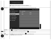
... Settings Press to select Auto Select, the monitor scans for your monitor. Select the VGA input when you are using the HDMI connector. Select HDMI input when you are using the analog (VGA) connector. Press Use Color Settings to select the VGA input source. Input Source NOTE: In most cases, ...
... Settings Press to select Auto Select, the monitor scans for your monitor. Select the VGA input when you are using the HDMI connector. Select HDMI input when you are using the analog (VGA) connector. Press Use Color Settings to select the VGA input source. Input Source NOTE: In most cases, ...
User's Guide
Page 36
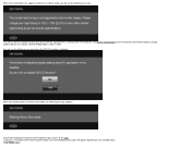
... and Vertical frequency ranges addressable by this monitor. Recommended mode is receiving from the computer. If you will appear depending on the selected input: VGA/HDMI input When the monitor does not support a particular resolution mode, you press any button other than the power button, one of the following message: This...
... and Vertical frequency ranges addressable by this monitor. Recommended mode is receiving from the computer. If you will appear depending on the selected input: VGA/HDMI input When the monitor does not support a particular resolution mode, you press any button other than the power button, one of the following message: This...

User's Guide
Page 37
If either VGA, or HDMI input is selected and the corresponding cable is recommended that you will see the message as shown below . or It is not connected, a floating dialog box as shown below appears. If not, you use the supplied power adapter. See Solving Problems for the monitor: Windows Vista®, Windows® 7, Windows® 8: Setting the Maximum Resolution To set the maximum resolution for more information.
If either VGA, or HDMI input is selected and the corresponding cable is recommended that you will see the message as shown below . or It is not connected, a floating dialog box as shown below appears. If not, you use the supplied power adapter. See Solving Problems for the monitor: Windows Vista®, Windows® 7, Windows® 8: Setting the Maximum Resolution To set the maximum resolution for more information.
User's Guide
Page 41
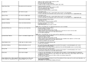
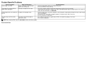
...via OSD. Perform Auto Adjust via OSD. Check for bent or broken pins in the video cable connector. NOTE: When using HDMI input, the positioning adjustments are not available. Perform monitor self-test feature check to Factory Settings. Check for bent or broken pins... are not available. For more information on Dell Monitor Quality and Pixel Policy, see Dell Support site at : support.dell.com. Adjust brightness & contrast controls via OSD. Check for more information, see Dell Support site at : support.dell.com. Contact Dell immediately. Ensure that can occur in use ...
...via OSD. Perform Auto Adjust via OSD. Check for bent or broken pins in the video cable connector. NOTE: When using HDMI input, the positioning adjustments are not available. Perform monitor self-test feature check to Factory Settings. Check for bent or broken pins... are not available. For more information on Dell Monitor Quality and Pixel Policy, see Dell Support site at : support.dell.com. Adjust brightness & contrast controls via OSD. Check for more information, see Dell Support site at : support.dell.com. Contact Dell immediately. Ensure that can occur in use ...
User's Guide
Page 42
Ensure the Computer is blue. NOTE: When choosing HDMI mode, the Auto Adjust function will not be available. Re-plug the signal cable if necessary. Back to different video formats (aspect ratio) of the ...
Ensure the Computer is blue. NOTE: When choosing HDMI mode, the Auto Adjust function will not be available. Re-plug the signal cable if necessary. Back to different video formats (aspect ratio) of the ...


