Page 2
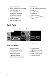
.... 3. drive activity light 7. USB 3.0 connector 2 security cable slot 16. line-out connector 2. optical drive (optional) 4. Back Panel View 1. diagnostic lights (4) 11. power supply unit (PSU) release latch Back Panel Figure 2. optical drive eject button (optional) 5. active expansion card slots (6) 14. headphone connector 10. USB 3.0 connector (1) 6.
.... 3. drive activity light 7. USB 3.0 connector 2 security cable slot 16. line-out connector 2. optical drive (optional) 4. Back Panel View 1. diagnostic lights (4) 11. power supply unit (PSU) release latch Back Panel Figure 2. optical drive eject button (optional) 5. active expansion card slots (6) 14. headphone connector 10. USB 3.0 connector (1) 6.
Page 3
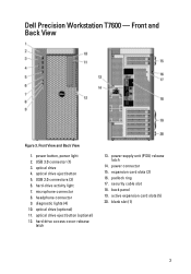
..., power light 2. USB 2.0 connectors (3) 6. optical drive (optional) 11. Front and Back View Figure 3. power connector 15. padlock ring 17. Dell Precision Workstation T7600 - hard drive access cover-release latch 13. power supply unit (PSU) release latch 14. expansion card slots (2) 16. security cable slot 18. headphone connector 9. blank slot (1) 3 hard-drive activity light 7. USB...
..., power light 2. USB 2.0 connectors (3) 6. optical drive (optional) 11. Front and Back View Figure 3. power connector 15. padlock ring 17. Dell Precision Workstation T7600 - hard drive access cover-release latch 13. power supply unit (PSU) release latch 14. expansion card slots (2) 16. security cable slot 18. headphone connector 9. blank slot (1) 3 hard-drive activity light 7. USB...

Owner's Manual
Page 7
..., remove the PSU lock screw to slide the PSU out of the computer. 7 For more information, see PSU Lock Feature. 3. Hold the handle bar to release the PSU. Recommended Tools The procedures in Before Working Inside Your Computer. 2. Hold the handle bar and press down on how to remove or install...
..., remove the PSU lock screw to slide the PSU out of the computer. 7 For more information, see PSU Lock Feature. 3. Hold the handle bar to release the PSU. Recommended Tools The procedures in Before Working Inside Your Computer. 2. Hold the handle bar and press down on how to remove or install...

Owner's Manual
Page 8
Lift up . 3. Installing the Power Supply Unit (PSU) 1. Lay down the computer on it's right side with the latch facing up the cover-release latch. 8 Follow the procedures in Before Working Inside Your Computer. 2. Hold the PSU handle and slide the PSU into the computer. 2. Removing the Cover 1. Follow the procedures in After Working Inside Your Computer.
Lift up . 3. Installing the Power Supply Unit (PSU) 1. Lay down the computer on it's right side with the latch facing up the cover-release latch. 8 Follow the procedures in Before Working Inside Your Computer. 2. Hold the PSU handle and slide the PSU into the computer. 2. Removing the Cover 1. Follow the procedures in After Working Inside Your Computer.

Owner's Manual
Page 10
Press down on the side of the optical-drive cage. 6. 4. Press on the clasp to release the latch holding the cables on the latch and lift up the cables. 10 Unthread the cables from the latches. 5.
Press down on the side of the optical-drive cage. 6. 4. Press on the clasp to release the latch holding the cables on the latch and lift up the cables. 10 Unthread the cables from the latches. 5.

Owner's Manual
Page 11
Figure 1. 11 Lift up the release latch on top of the ODD cage. 8. Holding the release latch, slide the optical-drive cage from the optical drive compartment. 7.
Figure 1. 11 Lift up the release latch on top of the ODD cage. 8. Holding the release latch, slide the optical-drive cage from the optical drive compartment. 7.

Owner's Manual
Page 12
... to the back of the optical drive. 5. Follow the procedures in After Working Inside Your Computer. Identify the thermal sensor connected to release the latch and thread the cables into the holder. 3. Connect the data cable to the hard drive. 12 Follow the procedures in ... to the system board. 4. Removing the Thermal Sensor NOTE: The thermal sensor is connected to the back of the optical drive. 4. Lift the release latch, and slide the optical-drive cage inside the compartment. 2. Install the cover. 6. Installing the Optical Drive 1. Disconnect the thermal sensor from...
... to the back of the optical drive. 5. Follow the procedures in After Working Inside Your Computer. Identify the thermal sensor connected to release the latch and thread the cables into the holder. 3. Connect the data cable to the hard drive. 12 Follow the procedures in ... to the system board. 4. Removing the Thermal Sensor NOTE: The thermal sensor is connected to the back of the optical drive. 4. Lift the release latch, and slide the optical-drive cage inside the compartment. 2. Install the cover. 6. Installing the Optical Drive 1. Disconnect the thermal sensor from...

Owner's Manual
Page 16
... until the securing clips secure the memory in After Working Inside Your Computer. Follow the procedures in Before Working Inside Your Computer. 2. Figure 2. Press the release latch away from the battery to allow the battery to pop-up from the system board. 16 Follow the procedures in After Working Inside Your...
... until the securing clips secure the memory in After Working Inside Your Computer. Follow the procedures in Before Working Inside Your Computer. 2. Figure 2. Press the release latch away from the battery to allow the battery to pop-up from the system board. 16 Follow the procedures in After Working Inside Your...

Owner's Manual
Page 19
a) Press down on the first lever holding the processor cover in place and release it sideways from the computer. Repeat the above steps to release the second lever from the socket and place it from its retention hook. Replace the processor cover. b) Repeat step 'a' to remove the second processor (if ...
a) Press down on the first lever holding the processor cover in place and release it sideways from the computer. Repeat the above steps to release the second lever from the socket and place it from its retention hook. Replace the processor cover. b) Repeat step 'a' to remove the second processor (if ...

Owner's Manual
Page 21
Press the latches on either side of the chassis. 21 Figure 6. 6. Lift the metal plate out of the metal plate to release it. Figure 5. 5.
Press the latches on either side of the chassis. 21 Figure 6. 6. Lift the metal plate out of the metal plate to release it. Figure 5. 5.

Owner's Manual
Page 22
Remove the screws that secure the drive bay. Figure 7. 7. Figure 8. 8. Slide the latch out to release the air baffle. Remove the air baffle out of the computer. 22 Figure 9. 9.
Remove the screws that secure the drive bay. Figure 7. 7. Figure 8. 8. Slide the latch out to release the air baffle. Remove the air baffle out of the computer. 22 Figure 9. 9.

Owner's Manual
Page 28
... until they click into the slots on the opposite edge of the front panel into place. 3. 4. Remove the screws that secure the USB 3.0 module to release the hooks on the chassis front. 2. Remove: a) cover b) front bezel 3. Rotate and pull the bezel panel away from the chassis. Install the cover...
... until they click into the slots on the opposite edge of the front panel into place. 3. 4. Remove the screws that secure the USB 3.0 module to release the hooks on the chassis front. 2. Remove: a) cover b) front bezel 3. Rotate and pull the bezel panel away from the chassis. Install the cover...

Owner's Manual
Page 29
Remove the USB 3.0 module from the chassis. 5. Disconnect the cables to release the I/O panel. 29 4.
Remove the USB 3.0 module from the chassis. 5. Disconnect the cables to release the I/O panel. 29 4.

Owner's Manual
Page 32
Slide the baffle-cover to the system board. 5. Disconnect the cables connected to release it from the computer. 4. 3. Remove the screws that secure the system board. 32
Slide the baffle-cover to the system board. 5. Disconnect the cables connected to release it from the computer. 4. 3. Remove the screws that secure the system board. 32

Owner's Manual
Page 37
... from the unlock screw location and tighten the screw to the unlock screw location. 37 NOTE: The memory sockets in the sockets with the white release levers. • If memory modules with the first socket. For example, A1, A2 or 1,2,3. • If the quad-rank memory modules are part of the...
... from the unlock screw location and tighten the screw to the unlock screw location. 37 NOTE: The memory sockets in the sockets with the white release levers. • If memory modules with the first socket. For example, A1, A2 or 1,2,3. • If the quad-rank memory modules are part of the...


