
Dell Precision Workstation R7610 Owner's Manual
Page 7
... be replaced or--if purchased separately--installed by a certified service technician. Turn off your computer and all network cables from the network device. 3. As you begin working inside the computer. 1. Press and hold the power button while the computer is unplugged to prevent the computer cover from being scratched. 2. CAUTION: Handle components and cards with your computer. Hold a component such as directed by its pins...
... be replaced or--if purchased separately--installed by a certified service technician. Turn off your computer and all network cables from the network device. 3. As you begin working inside the computer. 1. Press and hold the power button while the computer is unplugged to prevent the computer cover from being scratched. 2. CAUTION: Handle components and cards with your computer. Hold a component such as directed by its pins...

Dell Precision Workstation R7610 Owner's Manual
Page 9
CAUTION: To connect a network cable, first plug the cable into the network device and then plug it into the computer. 2. Connect any telephone or network cables to their electrical outlets. 4. Connect your computer and all attached devices to your computer. 5. If required, verify that the computer works correctly by running the Dell Diagnostics. 9 Turn on your computer. 3.
CAUTION: To connect a network cable, first plug the cable into the network device and then plug it into the computer. 2. Connect any telephone or network cables to their electrical outlets. 4. Connect your computer and all attached devices to your computer. 5. If required, verify that the computer works correctly by running the Dell Diagnostics. 9 Turn on your computer. 3.

Dell Precision Workstation R7610 Owner's Manual
Page 35
cover - Connect the control panel cables. 2. front bezel. 5. Install the screws that secures the control panel. 4. Replace the torx screw that secure the control panel. 3. Follow the procedures in After Working Inside Your Computer. 14 35 Installing the Control Panel 1. Install : -
cover - Connect the control panel cables. 2. front bezel. 5. Install the screws that secures the control panel. 4. Replace the torx screw that secure the control panel. 3. Follow the procedures in After Working Inside Your Computer. 14 35 Installing the Control Panel 1. Install : -

Dell Precision Workstation R7610 Owner's Manual
Page 39
Replace the plastic cover by securing the tabs on one side to the metal hinges and by pressing down the other side until it clicks into the drive bay. 2. cover - front bezel 5. cooling shroud - 16 Installing the Optical Drive 1. Connect the power and data cables. 3. Insert the optical drive into place. 4. Install: - Follow the procedures in After Working Inside Your Computer. 39
Replace the plastic cover by securing the tabs on one side to the metal hinges and by pressing down the other side until it clicks into the drive bay. 2. cover - front bezel 5. cooling shroud - 16 Installing the Optical Drive 1. Connect the power and data cables. 3. Insert the optical drive into place. 4. Install: - Follow the procedures in After Working Inside Your Computer. 39

Dell Precision Workstation R7610 Owner's Manual
Page 47
hard-drive assembly - cooling shroud - cover - Connect the SAS cables. 3. hard-drive carrier - Push the blue release tabs and insert the backplane in After Working Inside Your Computer. 47 optical drive - front bezel 4. Install: - Follow the procedures in the slot on the system board along the hard-drive assembly. 2. 20 Installing the SAS (Serial Attached SCSI) backplane 1.
hard-drive assembly - cooling shroud - cover - Connect the SAS cables. 3. hard-drive carrier - Push the blue release tabs and insert the backplane in After Working Inside Your Computer. 47 optical drive - front bezel 4. Install: - Follow the procedures in the slot on the system board along the hard-drive assembly. 2. 20 Installing the SAS (Serial Attached SCSI) backplane 1.

Dell Precision Workstation R7610 Owner's Manual
Page 85
hard-drive assembly - Follow the procedures in After Working Inside Your Computer. 38 85 Install: - front bezel 7. Installing the Power-Distribution Unit 1. cover - Slide the front chassis assembly to its original position. 6. fan bracket - cooling shroud - Connect the CPU 1, CPU 2, SAS Backplane and optical driver power connectors. 5. system fans - Install the screws that secure the power distribution unit. 3. expansion card cages - Place the power-distribution unit on the computer. 2. Route all the power cables through their routing channels. 4.
hard-drive assembly - Follow the procedures in After Working Inside Your Computer. 38 85 Install: - front bezel 7. Installing the Power-Distribution Unit 1. cover - Slide the front chassis assembly to its original position. 6. fan bracket - cooling shroud - Connect the CPU 1, CPU 2, SAS Backplane and optical driver power connectors. 5. system fans - Install the screws that secure the power distribution unit. 3. expansion card cages - Place the power-distribution unit on the computer. 2. Route all the power cables through their routing channels. 4.
Dell Precision Workstation R7610 Owner's Manual
Page 102
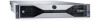
... system board. • If the LED next to drain. Allow one minute for the power to the switch does not illuminate, disconnect all internal and external peripherals, and press and hold the power supply test button at the rear of the power supply unit. Unplug the computer. Light Pattern Diagnostic LEDs Power Button LED Problem Description Troubleshooting Steps device, such as a lamp. • Ensure that the main power cable and front panel cable are securely connected to...
... system board. • If the LED next to drain. Allow one minute for the power to the switch does not illuminate, disconnect all internal and external peripherals, and press and hold the power supply test button at the rear of the power supply unit. Unplug the computer. Light Pattern Diagnostic LEDs Power Button LED Problem Description Troubleshooting Steps device, such as a lamp. • Ensure that the main power cable and front panel cable are securely connected to...
Dell Precision Workstation R7610 Owner's Manual
Page 103
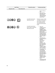
... the power supply unit. 103 Replace the CPU with the power supply. If the computer still fails to a different DIMM connector and re-start the computer. A possible system board failure has occurred. If the computer boots, add the peripheral cards back one by one until you find the bad one memory module is operating normally but the BIOS may be corrupt or missing. Light Pattern Diagnostic LEDs Power Button LED Problem Description Troubleshooting Steps problem...
... the power supply unit. 103 Replace the CPU with the power supply. If the computer still fails to a different DIMM connector and re-start the computer. A possible system board failure has occurred. If the computer boots, add the peripheral cards back one by one until you find the bad one memory module is operating normally but the BIOS may be corrupt or missing. Light Pattern Diagnostic LEDs Power Button LED Problem Description Troubleshooting Steps problem...

Dell Precision Workstation R7610 Owner's Manual
Page 104
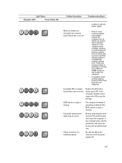
... boots, add the peripheral cards back one by one until you find the bad one. Light Pattern Diagnostic LEDs Power Button LED Problem Description Troubleshooting Steps Possible peripheral card or system board failure has occurred. A possible coin cell battery failure has occurred. Remove all internal and external peripherals, and restart the computer. lights are installed, remove the modules (see your service manual), then reinstall one minute, reinstall the battery, and restart. A possible processor failure Re-seat the processor...
... boots, add the peripheral cards back one by one until you find the bad one. Light Pattern Diagnostic LEDs Power Button LED Problem Description Troubleshooting Steps Possible peripheral card or system board failure has occurred. A possible coin cell battery failure has occurred. Remove all internal and external peripherals, and restart the computer. lights are installed, remove the modules (see your service manual), then reinstall one minute, reinstall the battery, and restart. A possible processor failure Re-seat the processor...
Dell Precision Workstation R7610 Owner's Manual
Page 105
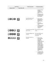
... display/monitor is plugged into a discrete graphic card. • Re-seat any installed graphics cards. • If available, install a working graphics card into your computer. A possible USB failure has occurred Re-install all USB devices and check all power and data has occurred. If the computer starts normally, continue to install additional memory modules (one module and restart the computer. Light Pattern Diagnostic LEDs Power Button LED Problem Description Troubleshooting Steps identified a faulty module or reinstalled all modules without error...
... display/monitor is plugged into a discrete graphic card. • Re-seat any installed graphics cards. • If available, install a working graphics card into your computer. A possible USB failure has occurred Re-install all USB devices and check all power and data has occurred. If the computer starts normally, continue to install additional memory modules (one module and restart the computer. Light Pattern Diagnostic LEDs Power Button LED Problem Description Troubleshooting Steps identified a faulty module or reinstalled all modules without error...

Dell Precision Workstation R7610 Owner's Manual
Page 106
... card installed. If the computer boots, add the peripheral cards back one . • If the problem persists, the system board / system board component is faulty. • Ensure that the memory you removed, then remove a different card and restart the computer. • Repeat this process for resource conflicts. • Clear CMOS. • Disconnect all internal and external peripherals, and restart the computer. Light Pattern Diagnostic LEDs Power Button LED Problem Description Memory modules are using is plugged...
... card installed. If the computer boots, add the peripheral cards back one . • If the problem persists, the system board / system board component is faulty. • Ensure that the memory you removed, then remove a different card and restart the computer. • Repeat this process for resource conflicts. • Clear CMOS. • Disconnect all internal and external peripherals, and restart the computer. Light Pattern Diagnostic LEDs Power Button LED Problem Description Memory modules are using is plugged...

Dell Precision Workstation R7610 Owner's Manual
Page 107
... boot from a device (such as the floppy drive or optical drive), check system setup to enter the system setup: • Alert! Processor Type Mismatch. • Alert! Incompatible Processor detected. Error Messages Errors That Halt the System Completely The following is a list of the system and the user will halt the system completely, requiring you to cycle the system's power: • Error! Memory configured incorrectly. CPU 0 fan failure. 107 Processor Speed Mismatch. • Alert! Card-cage fan failure...
... boot from a device (such as the floppy drive or optical drive), check system setup to enter the system setup: • Alert! Processor Type Mismatch. • Alert! Incompatible Processor detected. Error Messages Errors That Halt the System Completely The following is a list of the system and the user will halt the system completely, requiring you to cycle the system's power: • Error! Memory configured incorrectly. CPU 0 fan failure. 107 Processor Speed Mismatch. • Alert! Card-cage fan failure...
Dell Precision Workstation R7610 Owner's Manual
Page 112
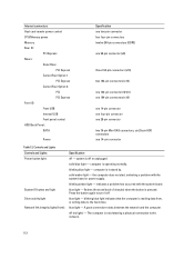
...light - flashes (front and back of chassis) when the button is operating normally. off - Internal connectors Host card remote power control CPU/Memory power Memory Rear IO: PCI Express Risers: Outer Riser PCI Express Center Riser Option 1 PCI Express Center Riser Option 2: PCI PCI Express Front IO: Front USB Internal USB Front panel control HDD Back Panel : SATA Power Specification one two-pin connector four four-pin connectors twelve 240-pin connectors (DDR3) one 98-pin connector (x8) three 164-pin connectors (x16) two 164-pin connectors (x16) one 120-pin connector (32 bit) one 164-pin...
...light - flashes (front and back of chassis) when the button is operating normally. off - Internal connectors Host card remote power control CPU/Memory power Memory Rear IO: PCI Express Risers: Outer Riser PCI Express Center Riser Option 1 PCI Express Center Riser Option 2: PCI PCI Express Front IO: Front USB Internal USB Front panel control HDD Back Panel : SATA Power Specification one two-pin connector four four-pin connectors twelve 240-pin connectors (DDR3) one 98-pin connector (x8) three 164-pin connectors (x16) two 164-pin connectors (x16) one 120-pin connector (32 bit) one 164-pin...

Dell Precision Workstation R7610 Owner's Manual
Page 113
... 1023 W : 100 VAC to 120 VAC, 1100 W : 200 VAC to 240 VAC 1400 W : 200 VAC to 149 °F) 113 Controls and Lights Network link integrity lights (rear): Network activity lights Diagnostic lights: Specification green light - A good connection at 100 Mbs exists between the network and the computer. A good connection at 10 Mbs exists between the network and the computer. see the service manual for important voltage-setting information.
... 1023 W : 100 VAC to 120 VAC, 1100 W : 200 VAC to 240 VAC 1400 W : 200 VAC to 149 °F) 113 Controls and Lights Network link integrity lights (rear): Network activity lights Diagnostic lights: Specification green light - A good connection at 100 Mbs exists between the network and the computer. A good connection at 10 Mbs exists between the network and the computer. see the service manual for important voltage-setting information.
Dell Precision Workstation R7610 Owner's Manual
Page 115
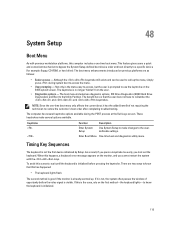
... diagnostics utility menu. The computer has several options available. When this happens, a keyboard error message appears on the first method-the keyboard lights-to know that the user does not have to restore the customer's boot order after completing troubleshooting. If it has the added benefit of opportunity before pressing the keystroke. 48 System Setup Boot Menu As with the keys. The boot menu enhancements introduced on the BIOS splash screen...
... diagnostics utility menu. The computer has several options available. When this happens, a keyboard error message appears on the first method-the keyboard lights-to know that the user does not have to restore the customer's boot order after completing troubleshooting. If it has the added benefit of opportunity before pressing the keystroke. 48 System Setup Boot Menu As with the keys. The boot menu enhancements introduced on the BIOS splash screen...

Dell Precision Workstation R7610 Owner's Manual
Page 116
... Board Displays the following fields are common for service replacement do not have the utility partition and therefore do not have this list. • USB Floppy Drive • Hard disk drive • CD/DVD/CD-RW Drive • Onboard or USB CD-ROM Drive • USB Device 116 Access these drives. Dell Diagnostics Factory-installed platforms include 32-bit system diagnostics on these diagnostics using the keystroke during system boot and select Diagnostics. Date/Time Boot Sequence Displays current date and time settings...
... Board Displays the following fields are common for service replacement do not have the utility partition and therefore do not have this list. • USB Floppy Drive • Hard disk drive • CD/DVD/CD-RW Drive • Onboard or USB CD-ROM Drive • USB Device 116 Access these drives. Dell Diagnostics Factory-installed platforms include 32-bit system diagnostics on these diagnostics using the keystroke during system boot and select Diagnostics. Date/Time Boot Sequence Displays current date and time settings...
Dell Precision Workstation R7610 Owner's Manual
Page 117
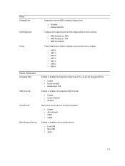
... Devices Enables or disables the integrated network card. Drives Diskette Drive SATA Operation Drives Determines how the BIOS configures floppy drives. • Disabled • Enabled (default) Configures the operating mode of the integrated hard-drive controller. • RAID Autodetect / AHCI • RAID Autodetect / ATA • RAID On (default) These fields let you enable or disable various drives in serial port operates. • Disable • Auto (default) • COM1 • COM3 Enables or disables various system devices. • Front USB • Rear USB • Audio...
... Devices Enables or disables the integrated network card. Drives Diskette Drive SATA Operation Drives Determines how the BIOS configures floppy drives. • Disabled • Enabled (default) Configures the operating mode of the integrated hard-drive controller. • RAID Autodetect / AHCI • RAID Autodetect / ATA • RAID On (default) These fields let you enable or disable various drives in serial port operates. • Disable • Auto (default) • COM1 • COM3 Enables or disables various system devices. • Front USB • Rear USB • Audio...

Dell Precision Workstation R7610 Owner's Manual
Page 120
... 2.0 Controls the SERR message mechanism. The options available are: • Disable (default) • Every Day • Weekdays NOTE: This feature does not work if you to automatically turn off your computer using the switch on when your computer. Enabled by default Allows speeding up remotely from Suspend, Hibernate, or Off. • Disable • Enable • Enable with Boot to NIC Displays the Service Tag of your computer starts. Enable Numlock LED - Enabled...
... 2.0 Controls the SERR message mechanism. The options available are: • Disable (default) • Every Day • Weekdays NOTE: This feature does not work if you to automatically turn off your computer using the switch on when your computer. Enabled by default Allows speeding up remotely from Suspend, Hibernate, or Off. • Disable • Enable • Enable with Boot to NIC Displays the Service Tag of your computer starts. Enable Numlock LED - Enabled...
Statement of Volatility
Page 1
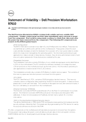
... as U_BIOS1 and U_BIOS2 on the motherboard such as thermal control. The Dell Precision Workstation R7610 contains both volatile and non-volatile (NV) components. PCH CMOS The PCH, identified as U_EC1 on the R7610 system board. It is identified as U_TPM) stores TPM configuration data used by the hardware and the security software offered by the user. BIOS Configuration The BIOS information is stored in this...
... as U_BIOS1 and U_BIOS2 on the motherboard such as thermal control. The Dell Precision Workstation R7610 contains both volatile and non-volatile (NV) components. PCH CMOS The PCH, identified as U_EC1 on the R7610 system board. It is identified as U_TPM) stores TPM configuration data used by the hardware and the security software offered by the user. BIOS Configuration The BIOS information is stored in this...
Statement of Volatility
Page 2
... and/or SATA Hard Drives and optional storage controller cards store non- In this state, the dynamic RAM is processed through cache (volatile) memory. volatile storage can readily be removed. Windows XP, Windows Vista and Windows 7 all of the data contained in the PCH (platform controller hub), including time- of displaying static data. The video BIOS is the shut off state. Any associated internal NVRAM is factory programmed, does...
... and/or SATA Hard Drives and optional storage controller cards store non- In this state, the dynamic RAM is processed through cache (volatile) memory. volatile storage can readily be removed. Windows XP, Windows Vista and Windows 7 all of the data contained in the PCH (platform controller hub), including time- of displaying static data. The video BIOS is the shut off state. Any associated internal NVRAM is factory programmed, does...


