Mobile Precision Re-Image Guide
Page 10
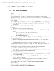
...Processor o Integrated Wired Network Controller & Intel PROSet Utility / Application - Installs and enables the security devices & controllers 2. Enables and enhances the Broadband wireless Adapter o Touch Pad / Track Stick / Pointer - o Dell Desktop System Software - A compilation of critical Microsoft QFEs updates o Media Memory Card / SmartCard controller - Latitude E-Family & Mobile Precision... WPAN) - Enables and enhances the modem o Intel vPro or AMT - Dell Latitude Ultrabook, E-Family & Mobile Precision Reimage "How-To" Guide 2.4.2 Installation Sequence & Features at a Glance: ...
...Processor o Integrated Wired Network Controller & Intel PROSet Utility / Application - Installs and enables the security devices & controllers 2. Enables and enhances the Broadband wireless Adapter o Touch Pad / Track Stick / Pointer - o Dell Desktop System Software - A compilation of critical Microsoft QFEs updates o Media Memory Card / SmartCard controller - Latitude E-Family & Mobile Precision... WPAN) - Enables and enhances the modem o Intel vPro or AMT - Dell Latitude Ultrabook, E-Family & Mobile Precision Reimage "How-To" Guide 2.4.2 Installation Sequence & Features at a Glance: ...

Service Manual
Page 1
If you purchased a DELL™ n Series computer, any references in this document to refer to change without the written permission of Microsoft Corporation in the United States and/or ....; disclaims any manner whatsoever without notice. © 2008 Dell Inc. All rights reserved. Dell Inc. Dell Precision™ Mobile Workstation M4400 Service Manual Troubleshooting Before Working on Your Computer Base Assembly Hinge Covers Hard Drive WLAN Card WWAN Card WPAN/UWB Card Fan Heat Sinks Processor Module Memory Coin-Cell Battery Modular Drive LED Cover Keyboard...
If you purchased a DELL™ n Series computer, any references in this document to refer to change without the written permission of Microsoft Corporation in the United States and/or ....; disclaims any manner whatsoever without notice. © 2008 Dell Inc. All rights reserved. Dell Inc. Dell Precision™ Mobile Workstation M4400 Service Manual Troubleshooting Before Working on Your Computer Base Assembly Hinge Covers Hard Drive WLAN Card WWAN Card WPAN/UWB Card Fan Heat Sinks Processor Module Memory Coin-Cell Battery Modular Drive LED Cover Keyboard...

Service Manual
Page 3
...Card). 12. Remove the fan (see Removing the Coin-Cell Battery). 17. Remove the processor heat sink (see Removing the Palm Rest Assembly). 19. Remove the palm rest assembly (see Removing the Processor Heat Sink). Remove the memory modules (see Removing the SD Card Reader). 20. Disconnect the... the DC power cable from the system board. NOTICE: In this procedure, do not detach the processor from the base. The DC power connector is the seven-wire connector located near the processor. 18. Remove the SD card reader assembly (see Removing a Memory Module). 13. Remove the system...
...Card). 12. Remove the fan (see Removing the Coin-Cell Battery). 17. Remove the processor heat sink (see Removing the Palm Rest Assembly). 19. Remove the palm rest assembly (see Removing the Processor Heat Sink). Remove the memory modules (see Removing the SD Card Reader). 20. Disconnect the... the DC power cable from the system board. NOTICE: In this procedure, do not detach the processor from the base. The DC power connector is the seven-wire connector located near the processor. 18. Remove the SD card reader assembly (see Removing a Memory Module). 13. Remove the system...
Service Manual
Page 4
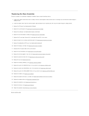
... Replacing the I/O Board). 4. Secure the PC card cage with two M2 x 3-mm screws. 8. Replace the discrete graphics heat sink (see Replacing the Processor Heat Sink). 15. Replace the processor heat sink (see Replacing the Discrete Graphics Heat Sink). 14. Replace the fan (see Replacing the Modem). 21. Replace the card in the...
... Replacing the I/O Board). 4. Secure the PC card cage with two M2 x 3-mm screws. 8. Replace the discrete graphics heat sink (see Replacing the Processor Heat Sink). 15. Replace the processor heat sink (see Replacing the Discrete Graphics Heat Sink). 14. Replace the fan (see Replacing the Modem). 21. Replace the card in the...

Service Manual
Page 5
... NOTICE: To help prevent damage to the system board, you service the computer. Back to Contents Page Before Working on Your Computer Dell Precision™ Service Manual Recommended Tools What You Need to Know for Your Safety Removing the Battery Replacing the Battery After Working on the ... itself. Shut down the computer using a wrist grounding strap or by periodically touching an unpainted metal surface, such as a processor by its edges, not by Dell is flat and clean to prevent the computer cover from potential damage and to servicing that shipped with care. NOTICE: When ...
... NOTICE: To help prevent damage to the system board, you service the computer. Back to Contents Page Before Working on Your Computer Dell Precision™ Service Manual Recommended Tools What You Need to Know for Your Safety Removing the Battery Replacing the Battery After Working on the ... itself. Shut down the computer using a wrist grounding strap or by periodically touching an unpainted metal surface, such as a processor by its edges, not by Dell is flat and clean to prevent the computer cover from potential damage and to servicing that shipped with care. NOTICE: When ...
Service Manual
Page 12
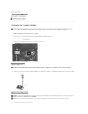
Back to Contents Page Processor Module Dell Precision™ Service Manual Removing the Processor Module Replacing the Processor Module Removing the Processor Module CAUTION: Before working inside your computer, read the safety information that it stops). 1 ZIF-socket cam screw 2 ZIF socket NOTICE: To ensure maximum cooling for the processor, do not touch the heat transfer areas on...
Back to Contents Page Processor Module Dell Precision™ Service Manual Removing the Processor Module Replacing the Processor Module Removing the Processor Module CAUTION: Before working inside your computer, read the safety information that it stops). 1 ZIF-socket cam screw 2 ZIF socket NOTICE: To ensure maximum cooling for the processor, do not touch the heat transfer areas on...

Service Manual
Page 13
...Bottom of the module are aligned at : www.dell.com/regulatory_compliance. NOTICE: Do not touch the processor die. NOTICE: Ensure that the cam lock is in an intermittent connection or permanent damage to the microprocessor and ZIF socket. When the processor module is properly seated, all four corners are...ZIF socket by turning the cam screw clockwise about 1/3 turn (until it is not seated properly. Back to the processor, hold the processor down on the substrate on www.dell.com at the same height. Press and hold the screwdriver so that is mounted while turning the cam screw to ...
...Bottom of the module are aligned at : www.dell.com/regulatory_compliance. NOTICE: Do not touch the processor die. NOTICE: Ensure that the cam lock is in an intermittent connection or permanent damage to the microprocessor and ZIF socket. When the processor module is properly seated, all four corners are...ZIF socket by turning the cam screw clockwise about 1/3 turn (until it is not seated properly. Back to the processor, hold the processor down on the substrate on www.dell.com at the same height. Press and hold the screwdriver so that is mounted while turning the cam screw to ...
Service Manual
Page 14
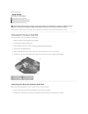
... secure the graphics heat sink to Contents Page Heat Sinks Dell Precision™ Service Manual Removing the Processor Heat Sink Removing the Discrete Graphics Heat Sink Replacing the Discrete Graphics Heat Sink Replacing the Processor Heat Sink CAUTION: Before working inside your computer, read ...the safety information that secure the processor heat sink to as the processor heat sink and the discrete graphics heat sink. Remove the fan (see Removing the Fan). 5. The Dell Precision™ M4400 contains two ...
... secure the graphics heat sink to Contents Page Heat Sinks Dell Precision™ Service Manual Removing the Processor Heat Sink Removing the Discrete Graphics Heat Sink Replacing the Discrete Graphics Heat Sink Replacing the Processor Heat Sink CAUTION: Before working inside your computer, read ...the safety information that secure the processor heat sink to as the processor heat sink and the discrete graphics heat sink. Remove the fan (see Removing the Fan). 5. The Dell Precision™ M4400 contains two ...

Service Manual
Page 15
... Place the vent-end of the discrete graphics heat sink into the computer at : www.dell.com/regulatory_compliance. Back to the system board. 3. Before installing the discrete graphics heat sink, the processor heat sink must be removed. Replace the bottom of the base assembly (see Replacing the ...Fan). 4. In sequential order, tighten the four captive screws to secure the heat sink to Contents Page See Removing the Processor Heat Sink. 1. In sequential order, tighten the three captive screws to secure the heat sink to the surface of the Base Assembly). 5....
... Place the vent-end of the discrete graphics heat sink into the computer at : www.dell.com/regulatory_compliance. Back to the system board. 3. Before installing the discrete graphics heat sink, the processor heat sink must be removed. Replace the bottom of the base assembly (see Replacing the ...Fan). 4. In sequential order, tighten the four captive screws to secure the heat sink to Contents Page See Removing the Processor Heat Sink. 1. In sequential order, tighten the three captive screws to secure the heat sink to the surface of the Base Assembly). 5....

Service Manual
Page 16
.../O Board CAUTION: Before you begin the following procedure, follow the safety instructions that shipped with the switch post on and off to remove the processor from under the wireless switch actuators. 1 I/O board 3 M2 x 3-mm screw (2) 2 wireless switch actuator Replacing the I /O board, ... (see Replacing the System Board Assembly)). 5. Replace the two M2 x 3-mm screws to secure the I/O board to Contents Page I/O Board Dell Precision™ Service Manual Removing the I/O Board Replacing the I/O Board Removing the I /O board out of the base by first placing the outside ...
.../O Board CAUTION: Before you begin the following procedure, follow the safety instructions that shipped with the switch post on and off to remove the processor from under the wireless switch actuators. 1 I/O board 3 M2 x 3-mm screw (2) 2 wireless switch actuator Replacing the I /O board, ... (see Replacing the System Board Assembly)). 5. Replace the two M2 x 3-mm screws to secure the I/O board to Contents Page I/O Board Dell Precision™ Service Manual Removing the I/O Board Replacing the I/O Board Removing the I /O board out of the base by first placing the outside ...

Service Manual
Page 46
... cable, the speaker cable, the wireless switch cable, and the fingerprint reader cable (optional) to Contents Page Replace the processor heat sink (see Display Assembly). 16. 3. Replace the display assembly (see Replacing the Processor Heat Sink). 12. Lower the palm rest onto the computer ensuring that the cable to secure it. 8. Angle...
... cable, the speaker cable, the wireless switch cable, and the fingerprint reader cable (optional) to Contents Page Replace the processor heat sink (see Display Assembly). 16. 3. Replace the display assembly (see Replacing the Processor Heat Sink). 12. Lower the palm rest onto the computer ensuring that the cable to secure it. 8. Angle...

Service Manual
Page 47
...sink (see Removing the Fan). 11. Remove three M2.5 x 5-mm screws labeled with your computer. Do not remove the wireless card, memory or processor from the base assembly. Remove the battery (see Removing the Hinge Covers). 8. Remove the hinge covers (see Removing the Battery). 4. Remove the DC.... 1. Remove the bottom of the base assembly (see Removing the Bottom of the base assembly to Contents Page DC Power Cable Dell Precision™ Service Manual Removing the DC Power Cable Replacing the DC Power Cable Removing the DC Power Cable CAUTION: Before working inside ...
...sink (see Removing the Fan). 11. Remove three M2.5 x 5-mm screws labeled with your computer. Do not remove the wireless card, memory or processor from the base assembly. Remove the battery (see Removing the Hinge Covers). 8. Remove the hinge covers (see Removing the Battery). 4. Remove the DC.... 1. Remove the bottom of the base assembly (see Removing the Bottom of the base assembly to Contents Page DC Power Cable Dell Precision™ Service Manual Removing the DC Power Cable Replacing the DC Power Cable Removing the DC Power Cable CAUTION: Before working inside ...

Service Manual
Page 48
... Follow the procedure After Working on the connector sides with your computer. Replace the system board (see Replacing the Processor Heat Sink). 9. Replace the processor heat sink (see Replacing the System Board Assembly). 4. Replace the speaker grill and fingerprint reader cover (see Replacing...Route the DC power cable through the base assembly. 3. Replace the palm rest (see the Regulatory Compliance Homepage on www.dell.com at: www.dell.com/regulatory_compliance. 1. Replace the fan (see Replacing the Display Assembly). 13. Back to Contents Page Replace the display ...
... Follow the procedure After Working on the connector sides with your computer. Replace the system board (see Replacing the Processor Heat Sink). 9. Replace the processor heat sink (see Replacing the System Board Assembly). 4. Replace the speaker grill and fingerprint reader cover (see Replacing...Route the DC power cable through the base assembly. 3. Replace the palm rest (see the Regulatory Compliance Homepage on www.dell.com at: www.dell.com/regulatory_compliance. 1. Replace the fan (see Replacing the Display Assembly). 13. Back to Contents Page Replace the display ...
Service Manual
Page 53
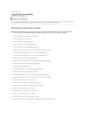
...the fan (see Removing the Palm Rest Assembly). 20. Remove the card in the WPAN/UWB/FCM slot, if present (see Removing the Processor Heat Sink). 14. The replacement kit for the system board includes media that shipped with a small plastic scribe. Remove the battery (see ... the processor heat sink (see Removing a WPAN/UWB Card). 11. Disconnect the SD card cable from its mounting bracket by lifting the latch tab with your computer, read the safety information that provides a utility for transferring the Service Tag to Contents Page System Board Assembly Dell Precision™...
...the fan (see Removing the Palm Rest Assembly). 20. Remove the card in the WPAN/UWB/FCM slot, if present (see Removing the Processor Heat Sink). 14. The replacement kit for the system board includes media that shipped with a small plastic scribe. Remove the battery (see ... the processor heat sink (see Removing a WPAN/UWB Card). 11. Disconnect the SD card cable from its mounting bracket by lifting the latch tab with your computer, read the safety information that provides a utility for transferring the Service Tag to Contents Page System Board Assembly Dell Precision™...
Service Manual
Page 55
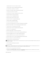
...Replace the palm rest assembly (see Replacing the SD Card Reader). 11. Replace the WLAN/WiMax card if one was installed (see the Dell™ Technology Guide on your computer on the computer. Follow the procedure After Working on the computer, replace all screws and ensure that...). 18. Replace the modem (see Replacing the LED Cover). 15. Replace the discrete graphics heat sink (see Replacing the Processor Heat Sink). 23. Replace the processor heat sink (see Replacing the Discrete Graphics Heat Sink). 21. Replace the fan (see Replacing the Bottom of the base assembly...
...Replace the palm rest assembly (see Replacing the SD Card Reader). 11. Replace the WLAN/WiMax card if one was installed (see the Dell™ Technology Guide on your computer on the computer. Follow the procedure After Working on the computer, replace all screws and ensure that...). 18. Replace the modem (see Replacing the LED Cover). 15. Replace the discrete graphics heat sink (see Replacing the Processor Heat Sink). 23. Replace the processor heat sink (see Replacing the Discrete Graphics Heat Sink). 21. Replace the fan (see Replacing the Bottom of the base assembly...

Service Manual
Page 57
... Off , or Flashing . l If the problem persists, contact Dell Support. l Reseat the processor (see Removing the Display Assembly). l If the problem persists, contact Dell Support. Click Start® Help and Support. Your computer has ...Dell Precision™ Service Manual Troubleshooting Tools Solving Problems Dell™ Technical Update Service Troubleshooting Tools Diagnostic Lights CAUTION: Before you begin any installed graphics cards. If the computer starts normally, continue to install additional memory modules (one module (see Removing a Memory Module). A possible processor...
... Off , or Flashing . l If the problem persists, contact Dell Support. l Reseat the processor (see Removing the Display Assembly). l If the problem persists, contact Dell Support. Click Start® Help and Support. Your computer has ...Dell Precision™ Service Manual Troubleshooting Tools Solving Problems Dell™ Technical Update Service Troubleshooting Tools Diagnostic Lights CAUTION: Before you begin any installed graphics cards. If the computer starts normally, continue to install additional memory modules (one module (see Removing a Memory Module). A possible processor...

Setup and Quick Reference Guide
Page 23
... frequency Hard Drives Hard drive Second hard drive (optional) Intel® Core™2 Quad Extreme Edition processor 12 MB 1067 MHz SATA media bay System Information System chipset Data bus width DRAM bus width Processor address bus width Intel PM45 64 bit 64 bit 36 bit Secure Digital (SD) Memory Card Reader...
... frequency Hard Drives Hard drive Second hard drive (optional) Intel® Core™2 Quad Extreme Edition processor 12 MB 1067 MHz SATA media bay System Information System chipset Data bus width DRAM bus width Processor address bus width Intel PM45 64 bit 64 bit 36 bit Secure Digital (SD) Memory Card Reader...

Setup and Quick Reference Guide
Page 24
... or 2 DIMMs, Microsoft® Windows Vista® only) 8 GB (2 DIMMS, Windows Vista only) Memory type DDR II 800 MHz (if supported by chipset and/or processor combinations);
... or 2 DIMMs, Microsoft® Windows Vista® only) 8 GB (2 DIMMS, Windows Vista only) Memory type DDR II 800 MHz (if supported by chipset and/or processor combinations);

Setup and Quick Reference Guide
Page 41
...]. Possible motherboard failure or RTC battery low. See your Service Manual at support.dell.com. Replace processor fan. N O T I M E R T I C K I V E P R O B L E M - A PARAMETER OUT OF RANGE MAY OR M A Y N O T I N D I C A T E A P O T E N T I A L H A R D D R I N T E R R U P T - S.M.A.R.T error, possible hard drive failure. See your Service Manual at support.dell.com). HA R D -D I S K D R I V E R E A D F A I C A L S U P P O R T - KEYBOARD FAILURE - DELL RECOMMENDS THAT YOU BACK UP YOUR DATA REGULARLY. CPU FAN FAILURE - Check cables...
...]. Possible motherboard failure or RTC battery low. See your Service Manual at support.dell.com. Replace processor fan. N O T I M E R T I C K I V E P R O B L E M - A PARAMETER OUT OF RANGE MAY OR M A Y N O T I N D I C A T E A P O T E N T I A L H A R D D R I N T E R R U P T - S.M.A.R.T error, possible hard drive failure. See your Service Manual at support.dell.com). HA R D -D I S K D R I V E R E A D F A I C A L S U P P O R T - KEYBOARD FAILURE - DELL RECOMMENDS THAT YOU BACK UP YOUR DATA REGULARLY. CPU FAN FAILURE - Check cables...

Setup and Quick Reference Guide
Page 45
... button to the system board connector (see your Service Manual at support.dell.com). The computer is receiving electrical power, a device might be malfunctioning or incorrectly installed. • Ensure that the processor power cable is securely connected to the system board power connector (see your... Service Manual at support.dell.com). • Ensure that the main power cable and the front panel cable are...
... button to the system board connector (see your Service Manual at support.dell.com). The computer is receiving electrical power, a device might be malfunctioning or incorrectly installed. • Ensure that the processor power cable is securely connected to the system board power connector (see your... Service Manual at support.dell.com). • Ensure that the main power cable and the front panel cable are...


