
Precision Tower 7810 Owners Manual
Page 3
... Installing the System-Fan Assembly...30 Removing the PSU Card...30 Installing the PSU Card...31 Removing the Speaker...32 Contents 3 PSU...11 Installing the Power Supply Unit - Contents Chapter 1: Working on your computer 5 Safety instructions...5 Before working inside your computer...5 Turning Off Your Computer...6 After working inside your computer...6 Chapter 2: Removing...
... Installing the System-Fan Assembly...30 Removing the PSU Card...30 Installing the PSU Card...31 Removing the Speaker...32 Contents 3 PSU...11 Installing the Power Supply Unit - Contents Chapter 1: Working on your computer 5 Safety instructions...5 Before working inside your computer...5 Turning Off Your Computer...6 After working inside your computer...6 Chapter 2: Removing...
Precision Tower 7810 Owners Manual
Page 4
... LEDs...49 Error Messages...51 Chapter 7: Technical Specifications 53 Chapter 8: Contacting Dell...58 4 Contents Installing the Speaker...32 System Board Components...32 Removing the System Board...33 Installing the System Board...35 Chapter 3: Additional Information 36 Memory Module Guidelines...36 Power Supply Unit - PSU Lock...36 Chapter 4: System Setup...38 Boot Sequence...38...
... LEDs...49 Error Messages...51 Chapter 7: Technical Specifications 53 Chapter 8: Contacting Dell...58 4 Contents Installing the Speaker...32 System Board Components...32 Removing the System Board...33 Installing the System Board...35 Chapter 3: Additional Information 36 Memory Module Guidelines...36 Power Supply Unit - PSU Lock...36 Chapter 4: System Setup...38 Boot Sequence...38...
Precision Tower 7810 Owners Manual
Page 8
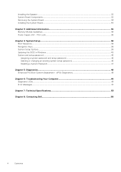
2 Removing and Installing Components This section provides detailed information on how to remove or install the components from your computer. PSU • Installing the Power Supply Unit - PSU • Removing the Computer Cover • Installing the Computer Cover • Removing the Front Bezel • Installing the Front Bezel • Removing the ... Tools The procedures in this document may require the following tools: 8 Removing and Installing Components Topics: • Recommended Tools • System Overview • Removing the Power Supply Unit -
2 Removing and Installing Components This section provides detailed information on how to remove or install the components from your computer. PSU • Installing the Power Supply Unit - PSU • Removing the Computer Cover • Installing the Computer Cover • Removing the Front Bezel • Installing the Front Bezel • Removing the ... Tools The procedures in this document may require the following tools: 8 Removing and Installing Components Topics: • Recommended Tools • System Overview • Removing the Power Supply Unit -
Precision Tower 7810 Owners Manual
Page 10
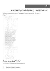
line-out connector 17. active expansion card slots 24. front bezel 4. graphics card 10 Removing and Installing Components PS/2 Mouse connector 21. mechanical slot 25. USB 3.0 connector 22. PSU cable shroud 7. hard drives 6. PS/2 Keyboard connector 15. USB 2.0 connector 23. power cable connector 26. 14. USB 3.0 connectors 16. optical drive 5. intrusion switch 2. padlock ring 19. network connector 20. Inside View of T7810 Computer 1. security cable slot 18. power-supply unit (PSU) release latch Figure 2. processor heatsink with integrated fan 3.
line-out connector 17. active expansion card slots 24. front bezel 4. graphics card 10 Removing and Installing Components PS/2 Mouse connector 21. mechanical slot 25. USB 3.0 connector 22. PSU cable shroud 7. hard drives 6. PS/2 Keyboard connector 15. USB 2.0 connector 23. power cable connector 26. 14. USB 3.0 connectors 16. optical drive 5. intrusion switch 2. padlock ring 19. network connector 20. Inside View of T7810 Computer 1. security cable slot 18. power-supply unit (PSU) release latch Figure 2. processor heatsink with integrated fan 3.

Precision Tower 7810 Owners Manual
Page 11
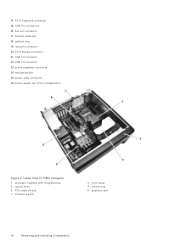
... 4. PCIe card retention Removing the Power Supply Unit - b. system board 3. PSU 1. For more information, see the PSU Lock Feature. 3. Hold the handle bar and press down on the blue latch to unlock ...
... 4. PCIe card retention Removing the Power Supply Unit - b. system board 3. PSU 1. For more information, see the PSU Lock Feature. 3. Hold the handle bar and press down on the blue latch to unlock ...
Precision Tower 7810 Owners Manual
Page 12
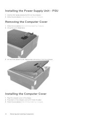
.... 2. Hold the PSU handle and slide the PSU into place. 3. Place the computer cover on the computer cover until it from the computer. Installing the Power Supply Unit -
.... 2. Hold the PSU handle and slide the PSU into place. 3. Place the computer cover on the computer cover until it from the computer. Installing the Power Supply Unit -
Precision Tower 7810 Owners Manual
Page 16
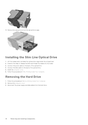
Remove the optical drive from the hard drive. 16 Removing and Installing Components Install the computer cover. 6. Disconnect the power supply and data cables from the optical-drive cage. Removing the Hard Drive 1. Press on the clasp to the back of the optical drive. 4. Follow the .... 3. Follow the procedures in After Working Inside Your Computer. 11. Lift the release latch, and slide the optical-drive cage inside the compartment. 2. Connect the power cable to the back of the optical drive. 5.
Remove the optical drive from the hard drive. 16 Removing and Installing Components Install the computer cover. 6. Disconnect the power supply and data cables from the optical-drive cage. Removing the Hard Drive 1. Press on the clasp to the back of the optical drive. 4. Follow the .... 3. Follow the procedures in After Working Inside Your Computer. 11. Lift the release latch, and slide the optical-drive cage inside the compartment. 2. Connect the power cable to the back of the optical drive. 5.
Precision Tower 7810 Owners Manual
Page 18
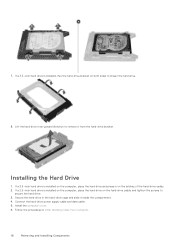
... hard drive on the hard-drive caddy and tighten the screws to remove it inside the compartment. 4. Install the computer cover. 6. Connect the hard-drive power supply cable and data cable. 5. If a 3.5-inch hard drive is installed on the computer, place the hard drive and press in an upward direction to secure...
... hard drive on the hard-drive caddy and tighten the screws to remove it inside the compartment. 4. Install the computer cover. 6. Connect the hard-drive power supply cable and data cable. 5. If a 3.5-inch hard drive is installed on the computer, place the hard drive and press in an upward direction to secure...

Precision Tower 7810 Owners Manual
Page 36
Topics: • Memory Module Guidelines • Power Supply Unit - NOTE: If all populated channels must have identical configurations. ● Memory modules must be installed beginning with different speeds are installed, they operate ... memory modules with the first socket. NOTE: Registered DIMMS (R-DIMMs) and Load Reduced DIMMS (LR-DIMMs) cannot be mixed (for example, 2 GB and 4 GB). Power Supply Unit - PSU Lock Memory Module Guidelines To ensure optimal performance of your computer, observe the following general guidelines when configuring your computer. Similarly, to unlock...
Topics: • Memory Module Guidelines • Power Supply Unit - NOTE: If all populated channels must have identical configurations. ● Memory modules must be installed beginning with different speeds are installed, they operate ... memory modules with the first socket. NOTE: Registered DIMMS (R-DIMMs) and Load Reduced DIMMS (LR-DIMMs) cannot be mixed (for example, 2 GB and 4 GB). Power Supply Unit - PSU Lock Memory Module Guidelines To ensure optimal performance of your computer, observe the following general guidelines when configuring your computer. Similarly, to unlock...
Precision Tower 7810 Owners Manual
Page 44
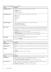
...speed up signal from the LAN or wireless LAN. ● LAN Only - Default Setting: Disabled Table 9. Fastboot Allows you to AC power supply. ● Disabled - Virtualization Support Option Description Virtualization This option specifies whether a Virtual Machine Monitor (VMM) can be enabled when the system boots.... ● Auto Table 10. Allows you to enable USB devices to the system in S4 and S5 Fan Speed Control Allows you to power on LAN Block Sleep This option allows the computer to sleep (S3 state) in the operating system. VT for Direct I /O Enables or...
...speed up signal from the LAN or wireless LAN. ● LAN Only - Default Setting: Disabled Table 9. Fastboot Allows you to AC power supply. ● Disabled - Virtualization Support Option Description Virtualization This option specifies whether a Virtual Machine Monitor (VMM) can be enabled when the system boots.... ● Auto Table 10. Allows you to enable USB devices to the system in S4 and S5 Fan Speed Control Allows you to power on LAN Block Sleep This option allows the computer to sleep (S3 state) in the operating system. VT for Direct I /O Enables or...
Precision Tower 7810 Owners Manual
Page 50
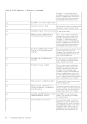
...drive cables are installed, remove the modules, then reinstall one at a time) until you have identified all peripheral cards from the power supply unit. 3,5 Memory modules are using is in recovery mode. 2,6 A possible processor failure has occurred Re-seat the processor 2,7 ...identified a faulty module or reinstalled all cable connections. 3,3 No memory modules installed If two or more memory modules are memory power failure has occurred. POST Diagnostic LED Patterns (continued) computer. battery. exist. If available, install working memory of the same...
...drive cables are installed, remove the modules, then reinstall one at a time) until you have identified all peripheral cards from the power supply unit. 3,5 Memory modules are using is in recovery mode. 2,6 A possible processor failure has occurred Re-seat the processor 2,7 ...identified a faulty module or reinstalled all cable connections. 3,3 No memory modules installed If two or more memory modules are memory power failure has occurred. POST Diagnostic LED Patterns (continued) computer. battery. exist. If available, install working memory of the same...
Precision Tower 7810 Owners Manual
Page 52
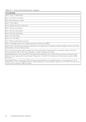
... module replacement is recommended. Alert! Correctable memory error has been detected in system memory. Your current power supply does not support the recent configuration changes made to the RMT Event log screen in system memory. Dell Reliable Memory Technology (RMT) has discovered and isolated errors in BIOS setup for specific DIMM information. Please...
... module replacement is recommended. Alert! Correctable memory error has been detected in system memory. Your current power supply does not support the recent configuration changes made to the RMT Event log screen in system memory. Dell Reliable Memory Technology (RMT) has discovered and isolated errors in BIOS setup for specific DIMM information. Please...
Precision Tower 7810 Owners Manual
Page 56
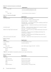
... exists between the network and the computer. Physical Feature Tower 7810 Height (with the system board. system is in standby. the computer does not start, indicating a problem with the system board or power supply. A good connection at 100 Mbps exists between the network ...and the computer orange light - Power Feature Specification Coin-cell battery Voltage Wattage Tower 7810 Maximum heat dissipation 825 W 685 W 3 V CR2032 lithium ...
... exists between the network and the computer. Physical Feature Tower 7810 Height (with the system board. system is in standby. the computer does not start, indicating a problem with the system board or power supply. A good connection at 100 Mbps exists between the network ...and the computer orange light - Power Feature Specification Coin-cell battery Voltage Wattage Tower 7810 Maximum heat dissipation 825 W 685 W 3 V CR2032 lithium ...


