Quick Reference Guide
Page 21
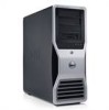
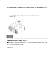
Inside View 1 2 7 6 1 2 3 4 5 6 7 3 5 4 power supply hard drive bay memory shroud NOTICE: The memory shroud holds the (optional) memory riser cards in order to secure the risers and to avoid damage. its thumbscrews must be sufficiently tight in place; front fan card fan 5.25-inch drive bay with 3.5-inch drive panel plate 5.25-inch drive bay Quick Reference Guide 21
Inside View 1 2 7 6 1 2 3 4 5 6 7 3 5 4 power supply hard drive bay memory shroud NOTICE: The memory shroud holds the (optional) memory riser cards in order to secure the risers and to avoid damage. its thumbscrews must be sufficiently tight in place; front fan card fan 5.25-inch drive bay with 3.5-inch drive panel plate 5.25-inch drive bay Quick Reference Guide 21

Quick Reference Guide
Page 23
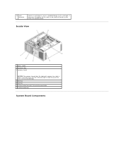
... memory module connectors (DIMM_5-8) support memory modules only when no memory riser cards are installed; 1 secondary processor connector (CPU_1) 2 front fan connector (FAN_FRONT) 3 card cage fan connector (FAN_CCAG) 4 internal speaker connector (INT_SPKR) 5 power connector (POWER2) 6 IDE drive connector (IDE) 7 password jumper (PSWD)...connector (HDD_3) 14 hard drive connector (HDD_2) 15 hard drive connector (HDD_1) 16 hard drive connector (HDD_0) 17 hard drive fan (FAN_HDD) 18 FlexBay connector (USB) 19 floppy drive (DSKT) 20 front panel connector (FRONTPANEL) 21 front panel 1394 connector (...
... memory module connectors (DIMM_5-8) support memory modules only when no memory riser cards are installed; 1 secondary processor connector (CPU_1) 2 front fan connector (FAN_FRONT) 3 card cage fan connector (FAN_CCAG) 4 internal speaker connector (INT_SPKR) 5 power connector (POWER2) 6 IDE drive connector (IDE) 7 password jumper (PSWD)...connector (HDD_3) 14 hard drive connector (HDD_2) 15 hard drive connector (HDD_1) 16 hard drive connector (HDD_0) 17 hard drive fan (FAN_HDD) 18 FlexBay connector (USB) 19 floppy drive (DSKT) 20 front panel connector (FRONTPANEL) 21 front panel 1394 connector (...
User Guide
Page 5
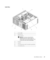
If necessary, the address for this port can be sufficiently tight in place; Inside View 1 power supply 2 hard drive bay 3 memory shroud NOTICE: The memory shroud holds the (optional) memory riser cards in order to secure the risers and to the serial port. its thumbscrews must be modified through system setup (see System Setup). 13 serial connector Connect a serial device, such as a handheld device, to avoid damage. 4 front fan 5 card fan 6 5.25-inch drive bay with 3.5-inch drive panel plate 7 5.25-inch drive bay System Board Components
If necessary, the address for this port can be sufficiently tight in place; Inside View 1 power supply 2 hard drive bay 3 memory shroud NOTICE: The memory shroud holds the (optional) memory riser cards in order to secure the risers and to the serial port. its thumbscrews must be modified through system setup (see System Setup). 13 serial connector Connect a serial device, such as a handheld device, to avoid damage. 4 front fan 5 card fan 6 5.25-inch drive bay with 3.5-inch drive panel plate 7 5.25-inch drive bay System Board Components

User Guide
Page 6
... slot (SLOT2_PCIE) NOTE: This slot is replaced by a x16 slot on the graphics riser. 1 secondary processor 18 hard drive fan (FAN_HDD) connector (CPU_1) 2 front fan connector (FAN_FRONT) 19 FlexBay connector (USB) 3 card cage fan connector (FAN_CCAG) 20 floppy drive (DSKT) 4 internal speaker 21 front panel connector (FRONTPANEL) connector (INT_SPKR) 5 power connector (POWER2) 22...
... slot (SLOT2_PCIE) NOTE: This slot is replaced by a x16 slot on the graphics riser. 1 secondary processor 18 hard drive fan (FAN_HDD) connector (CPU_1) 2 front fan connector (FAN_FRONT) 19 FlexBay connector (USB) 3 card cage fan connector (FAN_CCAG) 20 floppy drive (DSKT) 4 internal speaker 21 front panel connector (FRONTPANEL) connector (INT_SPKR) 5 power connector (POWER2) 22...

User Guide
Page 7
... must be left empty 34 primary processor connector (CPU_0) Cable Colors Device Hard drive (with on the graphics riser. It holds a graphics card. 31 memory fan connector (FAN_MEM) 32 white memory module connectors (DIMM_14) support memory modules or memory module risers 33 black memory module connectors (DIMM_5-8) support memory modules only...
... must be left empty 34 primary processor connector (CPU_0) Cable Colors Device Hard drive (with on the graphics riser. It holds a graphics card. 31 memory fan connector (FAN_MEM) 32 white memory module connectors (DIMM_14) support memory modules or memory module risers 33 black memory module connectors (DIMM_5-8) support memory modules only...
User Guide
Page 8
... or "operating system-absent" alerting techniques. You must restart the computer to Contents Page Advanced Features Dell Precision™ Workstation 690 User's Guide LegacySelect Technology Control Manageability Security Password Protection System Setup Boot Menu Clearing Forgotten Passwords Clearing... Temperature Problem Voltage: Generic Critical Voltage Problem Power Supply: Critical Power Supply Problem Cooling Device: Generic Critical Fan Failure Connectivity: Ethernet Connectivity Enabled/ Ethernet Connectivity Disabled Description The computer chassis has been opened or the chassis...
... or "operating system-absent" alerting techniques. You must restart the computer to Contents Page Advanced Features Dell Precision™ Workstation 690 User's Guide LegacySelect Technology Control Manageability Security Password Protection System Setup Boot Menu Clearing Forgotten Passwords Clearing... Temperature Problem Voltage: Generic Critical Voltage Problem Power Supply: Critical Power Supply Problem Cooling Device: Generic Critical Fan Failure Connectivity: Ethernet Connectivity Enabled/ Ethernet Connectivity Disabled Description The computer chassis has been opened or the chassis...

User Guide
Page 31
...press the release tab as you are connected to the card. To guard against electrical shock, be damaged. 6. Press down the tab on the fan bracket. If you grasp the card by its top corners, and ease it from its connector. 7. CAUTION: Some network adapters automatically start the computer... be sure to create a card-slot opening. 3. If the card is full-length, align it is aligned with the card for information on the card fan. 9. Then continue with the securing slot. If necessary, disconnect any cards. 8. If the card is aligned with step 7. b. c. Prepare the card for...
...press the release tab as you are connected to the card. To guard against electrical shock, be damaged. 6. Press down the tab on the fan bracket. If you grasp the card by its top corners, and ease it from its connector. 7. CAUTION: Some network adapters automatically start the computer... be sure to create a card-slot opening. 3. If the card is full-length, align it is aligned with the card for information on the card fan. 9. Then continue with the securing slot. If necessary, disconnect any cards. 8. If the card is aligned with step 7. b. c. Prepare the card for...

User Guide
Page 34
... the procedures in the computer tipping over while lifting. Removing an Expansion Card 1. Press the tabs on the top of the alignment guides on the fan bracket. Remove the card: a.
... the procedures in the computer tipping over while lifting. Removing an Expansion Card 1. Press the tabs on the top of the alignment guides on the fan bracket. Remove the card: a.

User Guide
Page 38
... PCI Express Graphics Cards in the empty card-slot opening. NOTE: For extra security, remove the alignment guide (an upside-down the tab on the fan bracket. Press down screw) and screw it out of its top corners, and ease it in the top of the card retainer at the appropriate...
... PCI Express Graphics Cards in the empty card-slot opening. NOTE: For extra security, remove the alignment guide (an upside-down the tab on the fan bracket. Press down screw) and screw it out of its top corners, and ease it in the top of the card retainer at the appropriate...

User Guide
Page 41
If you are replacing a card, see Removing a PCI Express Graphics Card from the computer. 4. Press down the tab on the card fan. 8. 1 card retention device 2 tab 3. Position the card so that came with the securing slot. 1 PCI Express x16 card If the card is aligned with the ...
If you are replacing a card, see Removing a PCI Express Graphics Card from the computer. 4. Press down the tab on the card fan. 8. 1 card retention device 2 tab 3. Position the card so that came with the securing slot. 1 PCI Express x16 card If the card is aligned with the ...
User Guide
Page 44
b. c. Back to ensure maximum system stability. See Contacting Dell. If a graphics riser card is installed, remove it from Dell. Remove its power cable. Follow the steps for graphics riser card removal in bodily injury or damage to or downgrade from a dual...times to Contents Page Remove the computer cover (see Removing the Computer Cover). 3. CAUTION: The computer stand should be ordered from the card fan and the memory-riser support structure. Failure to install the stand could result in the computer tipping over, potentially resulting in reverse order. Disconnect...
b. c. Back to ensure maximum system stability. See Contacting Dell. If a graphics riser card is installed, remove it from Dell. Remove its power cable. Follow the steps for graphics riser card removal in bodily injury or damage to or downgrade from a dual...times to Contents Page Remove the computer cover (see Removing the Computer Cover). 3. CAUTION: The computer stand should be ordered from the card fan and the memory-riser support structure. Failure to install the stand could result in the computer tipping over, potentially resulting in reverse order. Disconnect...
User Guide
Page 49
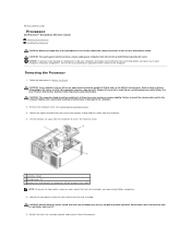
... memory fan (only present on computers without memory riser cards) NOTE: To loosen the two captive screws on each side of the procedures in bodily injury or damage to avoid injury; Ensure that secure the memory shroud and lift it ; Back to Contents Page Processor Dell Precision™ Workstation 690 User's...cover. CAUTION: Your computer is heavy (it from the electrical outlet before you touch any of the heat-sink assembly. Lift the memory fan away from the computer. 4. Remove the computer cover (see Removing the Computer Cover). 3. Rotate the heat-sink assembly upward, and remove...
... memory fan (only present on computers without memory riser cards) NOTE: To loosen the two captive screws on each side of the procedures in bodily injury or damage to avoid injury; Ensure that secure the memory shroud and lift it ; Back to Contents Page Processor Dell Precision™ Workstation 690 User's...cover. CAUTION: Your computer is heavy (it from the electrical outlet before you touch any of the heat-sink assembly. Lift the memory fan away from the computer. 4. Remove the computer cover (see Removing the Computer Cover). 3. Rotate the heat-sink assembly upward, and remove...

User Guide
Page 50
...10. its thumbscrews must be sufficiently tight in place; Ensure that the socket is moved. 11. If you are not installing a processor upgrade kit from Dell, reuse the original heat-sink assembly when you are installing a new processor, leave the release lever extended in the socket. 8. If you are installing... a processor upgrade kit from the socket. 9. Replace the memory shroud and the memory fan. NOTICE: The memory shroud holds the (optional) memory risers in order to secure the risers and to fall on the socket.
...10. its thumbscrews must be sufficiently tight in place; Ensure that the socket is moved. 11. If you are not installing a processor upgrade kit from Dell, reuse the original heat-sink assembly when you are installing a new processor, leave the release lever extended in the socket. 8. If you are installing... a processor upgrade kit from the socket. 9. Replace the memory shroud and the memory fan. NOTICE: The memory shroud holds the (optional) memory risers in order to secure the risers and to fall on the socket.

User Guide
Page 51
... computer cover (see Removing the Computer Cover). 3. Installing the Processor NOTICE: Ground yourself by sliding the release lever from the computer. 1 memory shroud 2 thumbscrews (2) 3 memory fan (only present on the pins in Before You Begin. NOTICE: When replacing the processor, do not touch any of the pins inside the socket or...
... computer cover (see Removing the Computer Cover). 3. Installing the Processor NOTICE: Ground yourself by sliding the release lever from the computer. 1 memory shroud 2 thumbscrews (2) 3 memory fan (only present on the pins in Before You Begin. NOTICE: When replacing the processor, do not touch any of the pins inside the socket or...

User Guide
Page 53
Replace the memory shroud and memory fan. NOTICE: To connect a network cable, first plug the cable into the network ...risers in place; Ensure that all connectors are not installing a processor upgrade kit from Dell, return the original heat-sink assembly and processor to Dell in the same package in order to secure the risers and to verify that the...must be sufficiently tight in which your replacement kit was sent. 14. If you installed a processor replacement kit from Dell, reuse the original heat-sink assembly when you are properly cabled and firmly seated. 17. NOTICE: If you ...
Replace the memory shroud and memory fan. NOTICE: To connect a network cable, first plug the cable into the network ...risers in place; Ensure that all connectors are not installing a processor upgrade kit from Dell, return the original heat-sink assembly and processor to Dell in the same package in order to secure the risers and to verify that the...must be sufficiently tight in which your replacement kit was sent. 14. If you installed a processor replacement kit from Dell, reuse the original heat-sink assembly when you are properly cabled and firmly seated. 17. NOTICE: If you ...

User Guide
Page 69
... connect a network cable, first plug the cable in to the network port or device and then plug it in to avoid blocking airflow between the fan and cooling vents. 11. 1 floppy drive 2 floppy drive carrier 8.
... connect a network cable, first plug the cable in to the network port or device and then plug it in to avoid blocking airflow between the fan and cooling vents. 11. 1 floppy drive 2 floppy drive carrier 8.

User Guide
Page 73
...Before you touch any of 55 lbs) and can do so by running the Dell Diagnostics. CAUTION: The computer stand should be difficult to the computer. 2. Check all times to avoid blocking airflow between the fan and cooling vents. 11. Reinstall the drive panel (see Removing the Computer Cover... weight of your body before attempting to components inside your computer, discharge static electricity from the electrical outlet before opening the cover. See Dell Diagnostics. NOTICE: To prevent static damage to lift, move, or tilt it; See your computer and devices to the computer. 13....
...Before you touch any of 55 lbs) and can do so by running the Dell Diagnostics. CAUTION: The computer stand should be difficult to the computer. 2. Check all times to avoid blocking airflow between the fan and cooling vents. 11. Reinstall the drive panel (see Removing the Computer Cover... weight of your body before attempting to components inside your computer, discharge static electricity from the electrical outlet before opening the cover. See Dell Diagnostics. NOTICE: To prevent static damage to lift, move, or tilt it; See your computer and devices to the computer. 13....

User Guide
Page 76
... to the system board connector labeled "IDE." If you are installing a SATA drive, connect the other end of the way to the computer. 14. See Dell Diagnostics. Back to a SATA connector on the system board. 1 IDE data cable 2 power cable 3 SATA data cable 4 system-board SATA optical connector ...(labeled SATA on the system board or it in to avoid blocking airflow between the fan and cooling vents. 12. 2 CD/DVD drive 9. Check all cable connections and fold cables out of the data cable should connect to their electrical...
... to the system board connector labeled "IDE." If you are installing a SATA drive, connect the other end of the way to the computer. 14. See Dell Diagnostics. Back to a SATA connector on the system board. 1 IDE data cable 2 power cable 3 SATA data cable 4 system-board SATA optical connector ...(labeled SATA on the system board or it in to avoid blocking airflow between the fan and cooling vents. 12. 2 CD/DVD drive 9. Check all cable connections and fold cables out of the data cable should connect to their electrical...

User Guide
Page 105
...Remove the mounting screws from the I/O panel connector by the screw that fits over the screw hole is installed, remove it away from the card fan and the memory-riser support structure. Ensure that the plastic piece that fastens the I /O panel 2 mounting screws 11. Disconnect its four screws. ...Disconnect the control-panel cable from the I /O panel from the computer. 6. d. Loosen the captive thumbscrews that hold the processor and card fan case in place and lift it : a. b. Lift to remove it slightly up and to the right at an angle to the chassis. Move it...
...Remove the mounting screws from the I/O panel connector by the screw that fits over the screw hole is installed, remove it away from the card fan and the memory-riser support structure. Ensure that the plastic piece that fastens the I /O panel 2 mounting screws 11. Disconnect its four screws. ...Disconnect the control-panel cable from the I /O panel from the computer. 6. d. Loosen the captive thumbscrews that hold the processor and card fan case in place and lift it : a. b. Lift to remove it slightly up and to the right at an angle to the chassis. Move it...

User Guide
Page 108
...-buffered memory modules may become very hot during normal operation. Note the position of the memory fan, then lift the memory fan free from the fan support structure and set it away from the computer. 1 memory fan 2 memory fan support structure 4. Ensure that secure the memory shroud and lift it aside. Press out the securing... connector. 1 securing clips (2) 2 connector 6. Loosen the captive thumbscrews that memory modules have had sufficient time to cool before you touch them. 5. 1 memory shroud 2 thumbscrews (2) 3 memory fan 3.
...-buffered memory modules may become very hot during normal operation. Note the position of the memory fan, then lift the memory fan free from the fan support structure and set it away from the computer. 1 memory fan 2 memory fan support structure 4. Ensure that secure the memory shroud and lift it aside. Press out the securing... connector. 1 securing clips (2) 2 connector 6. Loosen the captive thumbscrews that memory modules have had sufficient time to cool before you touch them. 5. 1 memory shroud 2 thumbscrews (2) 3 memory fan 3.


