Service Manual
Page 4
Removing the Dell Shield 39 Replacing the Dell Shield 40 Power Supply 41 Removing the Power Supply 41 Replacing the Power Supply 43 Computer Memory 45 System Memory Installation Guidelines 47 Removing a Memory Module 48 Installing a Memory Module 49 Removing Memory Riser Boards 50 Installing Memory Riser ...
Removing the Dell Shield 39 Replacing the Dell Shield 40 Power Supply 41 Removing the Power Supply 41 Replacing the Power Supply 43 Computer Memory 45 System Memory Installation Guidelines 47 Removing a Memory Module 48 Installing a Memory Module 49 Removing Memory Riser Boards 50 Installing Memory Riser ...

Service Manual
Page 9
...avoid touching pins on the computer chassis to dissipate any peripherals. NOTICE: Do not attempt to service the computer yourself, except as the power supply, to discharge any telephone or network lines from your body before touching anything inside your computer. Replace the battery only with the same...such as explained in the sequence indicated. Safety First-For You and Your Computer Use the following steps in your online Dell documentation or otherwise provided to you work, periodically touch an unpainted metal surface on a chip. 3 Disconnect your computer and peripherals from...
...avoid touching pins on the computer chassis to dissipate any peripherals. NOTICE: Do not attempt to service the computer yourself, except as the power supply, to discharge any telephone or network lines from your body before touching anything inside your computer. Replace the battery only with the same...such as explained in the sequence indicated. Safety First-For You and Your Computer Use the following steps in your online Dell documentation or otherwise provided to you work, periodically touch an unpainted metal surface on a chip. 3 Disconnect your computer and peripherals from...

Service Manual
Page 13
SECTION 2 Removing and Installing Parts Computer Cover Interior Service Label Inside Your Computer System Board Components Drive Door Front Panel Front-Panel Inserts Front-Panel Button Dell Shield Power Supply Computer Memory Disk Drives and Media Expansion-Card Airflow Shroud Expansion Cards Expansion-Card Cooling Fan and Guide Control Panel I/O Panel Chassis Intrusion Switch www.dell.com | support.dell.com
SECTION 2 Removing and Installing Parts Computer Cover Interior Service Label Inside Your Computer System Board Components Drive Door Front Panel Front-Panel Inserts Front-Panel Button Dell Shield Power Supply Computer Memory Disk Drives and Media Expansion-Card Airflow Shroud Expansion Cards Expansion-Card Cooling Fan and Guide Control Panel I/O Panel Chassis Intrusion Switch www.dell.com | support.dell.com
Service Manual
Page 21
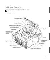
NOTE: User service access points are color-coded green. Inside Your Computer The following figure shows the computer with the cover open. Inside the Computer interior service label diskette drive bracket hard-drive bracket externally accessible-drive bracket chassis intrusion switch control panel memory riser board retention bracket (if needed) microprocessor airflow shroud I/O panel connectors expansion-card slots AGP card brace speaker expansion-card cooling fan system board power supply AC power receptacle power supply airflow vents 21
NOTE: User service access points are color-coded green. Inside Your Computer The following figure shows the computer with the cover open. Inside the Computer interior service label diskette drive bracket hard-drive bracket externally accessible-drive bracket chassis intrusion switch control panel memory riser board retention bracket (if needed) microprocessor airflow shroud I/O panel connectors expansion-card slots AGP card brace speaker expansion-card cooling fan system board power supply AC power receptacle power supply airflow vents 21
Service Manual
Page 41
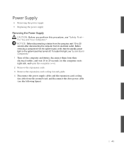
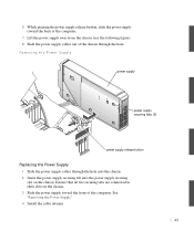
...from the computer, wait 10 to 20 seconds, lay the computer on the system board has turned off. Power Supply • Removing the power supply • Replacing the power supply Removing the Power Supply CAUTION: Before you perform this light, see "System Board Components." 1 Turn off the computer and devices,...expansion cards. 3 Remove the expansion-card cooling fan and guide. 4 Disconnect the power supply cables and the expansion-card cooling fan cable from the system board, and disconnect the drive power cable (see the following figure). 41 For You and Your Computer." To locate this...
...from the computer, wait 10 to 20 seconds, lay the computer on the system board has turned off. Power Supply • Removing the power supply • Replacing the power supply Removing the Power Supply CAUTION: Before you perform this light, see "System Board Components." 1 Turn off the computer and devices,...expansion cards. 3 Remove the expansion-card cooling fan and guide. 4 Disconnect the power supply cables and the expansion-card cooling fan cable from the system board, and disconnect the drive power cable (see the following figure). 41 For You and Your Computer." To locate this...

Service Manual
Page 42
b Slide the cable retainer to the right. c Lift the cable retainer out of the four securing slots in the chassis. 42 www.dell.com | support.dell.com Removing the Plastic Cable Retainer drive power cable cable retainer release button expansion-card cooling fan cable power supply cables 5 Remove the cable retainer. a Pull up on the cable retainer release button.
b Slide the cable retainer to the right. c Lift the cable retainer out of the four securing slots in the chassis. 42 www.dell.com | support.dell.com Removing the Plastic Cable Retainer drive power cable cable retainer release button expansion-card cooling fan cable power supply cables 5 Remove the cable retainer. a Pull up on the cable retainer release button.
Service Manual
Page 43
... their slots on the chassis. Removing the Power Supply power supply power supply securing tabs (5) power supply release button Replacing the Power Supply 1 Slide the power supply cables through the hole into the chassis. 2 Insert the power supply securing tab into the power supply securing slot on the chassis. 3 Slide the power supply toward the back of the computer. 7 Lift the power supply away from the chassis (see the following...
... their slots on the chassis. Removing the Power Supply power supply power supply securing tabs (5) power supply release button Replacing the Power Supply 1 Slide the power supply cables through the hole into the chassis. 2 Insert the power supply securing tab into the power supply securing slot on the chassis. 3 Slide the power supply toward the back of the computer. 7 Lift the power supply away from the chassis (see the following...

Service Manual
Page 44
www.dell.com | support.dell.com a Place the cable retainer into place. 5 Connect the power supply cables and the expansion-card cooling fan cable to the left until it locks into the four securing slots in the chassis. b Slide the cable retainer to the system board, and connect the drive power cable. 6 Replace the expansion-card cooling fan and guide. 7 Install the expansion cards. 8 Close the computer cover and restart the computer. 44
www.dell.com | support.dell.com a Place the cable retainer into place. 5 Connect the power supply cables and the expansion-card cooling fan cable to the left until it locks into the four securing slots in the chassis. b Slide the cable retainer to the system board, and connect the drive power cable. 6 Replace the expansion-card cooling fan and guide. 7 Install the expansion cards. 8 Close the computer cover and restart the computer. 44

Microprocessor Replacement
Page 7
... to dissipate any telephone or network lines from AC power before you work, periodically touch an unpainted metal surface on the back of the chassis. Microprocessor Replacement 5 Also avoid touching components or contacts on a card and avoid touching pins on the Dell Precision™ WorkStation 530 computer. Doing so reduces the potential for personal... of the computer or on procedures in the sequence indicated. 1 Turn off your operating system. For more information on the computer chassis, such as the power supply, to discharge any devices.
... to dissipate any telephone or network lines from AC power before you work, periodically touch an unpainted metal surface on the back of the chassis. Microprocessor Replacement 5 Also avoid touching components or contacts on a card and avoid touching pins on the Dell Precision™ WorkStation 530 computer. Doing so reduces the potential for personal... of the computer or on procedures in the sequence indicated. 1 Turn off your operating system. For more information on the computer chassis, such as the power supply, to discharge any devices.

Memory Riser Board Replacement
Page 5
...avoid touching pins on . If it to an unpainted metal surface, such as the power supply, to go out. Memory Riser Board Replacement 5 Also, disconnect any static electricity that the standby power light on the system board is not on a chip. 4 Verify that might harm...loop on the Dell Precision™ WorkStation 530 computer. Precautionary Measures Before you begin. NOTE: Dell recommends that you read this entire document before disconnecting the device or removing the component to avoid possible damage to dissipate any telephone or network lines from their power sources. If...
...avoid touching pins on . If it to an unpainted metal surface, such as the power supply, to go out. Memory Riser Board Replacement 5 Also, disconnect any static electricity that the standby power light on the system board is not on a chip. 4 Verify that might harm...loop on the Dell Precision™ WorkStation 530 computer. Precautionary Measures Before you begin. NOTE: Dell recommends that you read this entire document before disconnecting the device or removing the component to avoid possible damage to dissipate any telephone or network lines from their power sources. If...

Setup and Quick Reference Guide
Page 23
... cable retainer memory riser board retention bracket (if needed) AGP card brace speaker microprocessor airflow shroud I/O panel connectors expansion-card slots expansion-card cooling fan power supply system board AC power receptacle power supply airflow vents Setup and Quick Reference Guide 23 Inside Your Computer The following figure shows the computer with the cover open.
... cable retainer memory riser board retention bracket (if needed) AGP card brace speaker microprocessor airflow shroud I/O panel connectors expansion-card slots expansion-card cooling fan power supply system board AC power receptacle power supply airflow vents Setup and Quick Reference Guide 23 Inside Your Computer The following figure shows the computer with the cover open.
Setup and Quick Reference Guide
Page 31
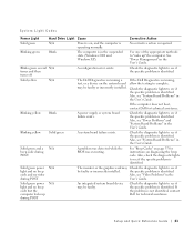
... to see if the specific problem is identified. Also, see "System Board Problems" in the User's Guide. Blinking yellow Blank A power supply or system board failure exists. Also, see "System Board Problems" in the User's Guide. Also, check the diagnostic lights to see... if the specific problem is identified. See "Power Management" in the User's Guide. If the Dell Diagnostics is not identified, contact Dell for technical assistance. Also, see if the specific problem is identified. If the problem is running ...
... to see if the specific problem is identified. Also, see "System Board Problems" in the User's Guide. Blinking yellow Blank A power supply or system board failure exists. Also, see "System Board Problems" in the User's Guide. Also, check the diagnostic lights to see... if the specific problem is identified. See "Power Management" in the User's Guide. If the Dell Diagnostics is not identified, contact Dell for technical assistance. Also, see if the specific problem is identified. If the problem is running ...
Setup and Quick Reference Guide
Page 33
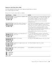
..." in the User's Guide. If the problem is still not resolved, contact Dell for technical assistance. If the problem is still not resolved, contact Dell for technical assistance. A B C D A B C D Possible power supply or power cord See "Power Problems" in the User's Guide. Possible system board failure. Diagnostic Light Codes Before POST The following table lists the codes...
..." in the User's Guide. If the problem is still not resolved, contact Dell for technical assistance. If the problem is still not resolved, contact Dell for technical assistance. A B C D A B C D Possible power supply or power cord See "Power Problems" in the User's Guide. Possible system board failure. Diagnostic Light Codes Before POST The following table lists the codes...


