
Tower Service Manual
Page 4
Installing the speaker...39 Coin cell battery...41 Removing the coin cell battery...41 Installing the coin cell battery...41 Power supply unit...42 Removing the power supply unit...42 Installing the power supply unit ...45 Optical drive...48 Removing the optical drive...48 Installing the optical drive...50 IO panel...51 Removing the IO panel...51......85 Removing intrusion switch...85 Installing intrusion switch...86 System board...87 Removing the system board...87 Installing the system board...89 Chapter 5: Troubleshooting...93 Power supply unit Built-in Self Test ...93 Steps to confirm that...
Installing the speaker...39 Coin cell battery...41 Removing the coin cell battery...41 Installing the coin cell battery...41 Power supply unit...42 Removing the power supply unit...42 Installing the power supply unit ...45 Optical drive...48 Removing the optical drive...48 Installing the optical drive...50 IO panel...51 Removing the IO panel...51......85 Removing intrusion switch...85 Installing intrusion switch...86 System board...87 Removing the system board...87 Installing the system board...89 Chapter 5: Troubleshooting...93 Power supply unit Built-in Self Test ...93 Steps to confirm that...

Tower Service Manual
Page 15
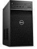
Bezel 8. Chasis 10. Cover 2. Power button module 5. IO panel 4. Optical drive 6. Hard drive 9. Power supply unit 11. Major components of components and their part numbers for purchase options. System fan 3. System board 12. These parts are available according to warranty coverages purchased by the customer. Contact your system 15 1. Front fan 13. Heatsink assembly NOTE: Dell provides a list of your Dell sales representative for the original system configuration purchased. Processor 14. Hard drive 7.
Bezel 8. Chasis 10. Cover 2. Power button module 5. IO panel 4. Optical drive 6. Hard drive 9. Power supply unit 11. Major components of components and their part numbers for purchase options. System fan 3. System board 12. These parts are available according to warranty coverages purchased by the customer. Contact your system 15 1. Front fan 13. Heatsink assembly NOTE: Dell provides a list of your Dell sales representative for the original system configuration purchased. Processor 14. Hard drive 7.

Tower Service Manual
Page 16
... • Hard drive • PSU hinge • Graphics card • Memory module • Speaker • Coin cell battery • Power supply unit • Optical drive • IO panel • Solid state drive • Power button module • Heatsink assembly • Blower and heat sink assembly • Voltage regulator heat sink • Front fan...
... • Hard drive • PSU hinge • Graphics card • Memory module • Speaker • Coin cell battery • Power supply unit • Optical drive • IO panel • Solid state drive • Power button module • Heatsink assembly • Blower and heat sink assembly • Voltage regulator heat sink • Front fan...

Tower Service Manual
Page 42
3. Remove: a. Cover b. Open the PSU hinge 4. Disconnect the CPU-power cable and system board power cable from the routing guide on the chassis [4]. 42 Disassembly and reassembly c. Follow the procedure in After working inside ...the following cables: ● For systems shipped with 65 W/80 W CPU system configurations: a. Unroute the CPU power cable from the system board [2,3]. Install the Cover. 5. b. Close the PSU hinge. 4. Power supply unit Removing the power supply unit 1. Follow the procedure in Before Working Inside Your Computer. 2. Disconnect the optical-drive...
3. Remove: a. Cover b. Open the PSU hinge 4. Disconnect the CPU-power cable and system board power cable from the routing guide on the chassis [4]. 42 Disassembly and reassembly c. Follow the procedure in After working inside ...the following cables: ● For systems shipped with 65 W/80 W CPU system configurations: a. Unroute the CPU power cable from the system board [2,3]. Install the Cover. 5. b. Close the PSU hinge. 4. Power supply unit Removing the power supply unit 1. Follow the procedure in Before Working Inside Your Computer. 2. Disconnect the optical-drive...

Tower Service Manual
Page 44
... reassembly d. Disconnect the wiring harness from the system [3]. Disconnect the hard-disk power cable [1]. Remove the two #6-32x1/4'' screws that secure the power-supply unit to the chassis [4]. c. Remove the four #6-32x1/4'' screws that secure the power-supply bracket to four hard-disk power cables depending on the quantity of hard-disk drive installed. Close the...
... reassembly d. Disconnect the wiring harness from the system [3]. Disconnect the hard-disk power cable [1]. Remove the two #6-32x1/4'' screws that secure the power-supply unit to the chassis [4]. c. Remove the four #6-32x1/4'' screws that secure the power-supply bracket to four hard-disk power cables depending on the quantity of hard-disk drive installed. Close the...

Tower Service Manual
Page 45
Disassembly and reassembly 45 Installing the power supply unit 1. Connect the wiring harness to the 95 W CPU system configuration.
Disassembly and reassembly 45 Installing the power supply unit 1. Connect the wiring harness to the 95 W CPU system configuration.

Tower Service Manual
Page 46
Connect the hard drive power cable [5] 46 Disassembly and reassembly Insert the PSU into the PSU slot and slide it towards the back of the computer until it clicks into place [1]. 3. Place the power supply bracket [3] and tighten the two #6-32x1/4'' screws to secure the PSU to the computer [2]. 4. Replace the four #6-32x1/4'' screws to secure the PSU to the computer [4]. 5. 2.
Connect the hard drive power cable [5] 46 Disassembly and reassembly Insert the PSU into the PSU slot and slide it towards the back of the computer until it clicks into place [1]. 3. Place the power supply bracket [3] and tighten the two #6-32x1/4'' screws to secure the PSU to the computer [2]. 4. Replace the four #6-32x1/4'' screws to secure the PSU to the computer [4]. 5. 2.

Tower Service Manual
Page 93
Steps to confirm that the power supply unit is functional. 5 Troubleshooting Topics: • Power supply unit Built-in Self Test (BIST). Disconnect the power cord from the power supply unit. ePSA diagnostics • Diagnostics • Diagnostic error messages • System error messages Power supply unit Built-in Self Test Precision 3630 supports a new power supply unit Built-in Self Test • Enhanced Pre-Boot...
Steps to confirm that the power supply unit is functional. 5 Troubleshooting Topics: • Power supply unit Built-in Self Test (BIST). Disconnect the power cord from the power supply unit. ePSA diagnostics • Diagnostics • Diagnostic error messages • System error messages Power supply unit Built-in Self Test Precision 3630 supports a new power supply unit Built-in Self Test • Enhanced Pre-Boot...

Tower Service Manual
Page 94
... The system is failing. The system is normal but another device in the lower-right corner to go to access the power-supply unit and its cables. 2. Replace the power supply unit. NOTE: The Enhanced Pre-boot System Assessment window displays, listing all the detected devices. 4. The detected items are... computer boots, press the F12 key when the Dell logo is launched by the BIOS internally. Select the device from the system board and other devices. ● If the LED does not turn on, it indicates that the power-supply unit is failing or not installed properly. 94 ...
... The system is failing. The system is normal but another device in the lower-right corner to go to access the power-supply unit and its cables. 2. Replace the power supply unit. NOTE: The Enhanced Pre-boot System Assessment window displays, listing all the detected devices. 4. The detected items are... computer boots, press the F12 key when the Dell logo is launched by the BIOS internally. Select the device from the system board and other devices. ● If the LED does not turn on, it indicates that the power-supply unit is failing or not installed properly. 94 ...
Tower Service Manual
Page 95
... coin cell battery 2,5 BIOS Recovery 2,6 CPU 2,7 Memory 3,3 Memory 3,5 Memory 3,6 BIOS Recovery 3,7 BIOS Recovery Faults Faulty system board Faulty system board, power supply unit (PSU), or cabling Faulty system board, power supply unit (PSU), or DIMMS Faulty coin cell battery AutoRecovery trigger, recovery image is not found or is invalid CPU Error Memory SPD..., put spaces in hibernation or turned off indicating the Recovery image is not found On-demand trigger, recovery image is not found . Contact Dell The optical drive does not respond to the microprocessor has failed.
... coin cell battery 2,5 BIOS Recovery 2,6 CPU 2,7 Memory 3,3 Memory 3,5 Memory 3,6 BIOS Recovery 3,7 BIOS Recovery Faults Faulty system board Faulty system board, power supply unit (PSU), or cabling Faulty system board, power supply unit (PSU), or DIMMS Faulty coin cell battery AutoRecovery trigger, recovery image is not found or is invalid CPU Error Memory SPD..., put spaces in hibernation or turned off indicating the Recovery image is not found On-demand trigger, recovery image is not found . Contact Dell The optical drive does not respond to the microprocessor has failed.

Tower Setup and Specifications Guide
Page 3
......11 Memory...13 Storage...13 Storage Matrix...14 Audio...14 Video card...14 Communication...15 Ports and connectors...15 Media card-reader...16 Power Supply...16 Physical system dimensions...17 Computer environment...17 Chapter 4: System setup...18 Boot menu...18 Navigation keys...18 System Setup options...18 ...BIOS in Windows ...25 Updating BIOS on systems with BitLocker enabled 26 Updating your system BIOS using a USB flash drive 26 Updating the Dell BIOS in Linux and Ubuntu environments 26 Flashing the BIOS from the F12 One-Time boot menu 27 System and setup password...29 Assigning...
......11 Memory...13 Storage...13 Storage Matrix...14 Audio...14 Video card...14 Communication...15 Ports and connectors...15 Media card-reader...16 Power Supply...16 Physical system dimensions...17 Computer environment...17 Chapter 4: System setup...18 Boot menu...18 Navigation keys...18 System Setup options...18 ...BIOS in Windows ...25 Updating BIOS on systems with BitLocker enabled 26 Updating your system BIOS using a USB flash drive 26 Updating the Dell BIOS in Linux and Ubuntu environments 26 Flashing the BIOS from the F12 One-Time boot menu 27 System and setup password...29 Assigning...

Tower Setup and Specifications Guide
Page 16
Table 10. Power Specifications Feature Energy efficient power supply 80 plus bronze certification 80 plus gold certification Recyclable packaging MultiPack packaging Specifications ● Two USB 2.0 Type-A port(Front) ● One USB 3.1 Gen 2 Type-C port (... W EPA bronze (No SD) 300 W / 460 W (w/SD) and 850 W(w/SD) Optional, US only No 16 System specifications Media-card reader specifications Feature Type Supported cards Power Supply Table 12. Ports and connectors (continued) Feature USB Security Audio Video Network adapter Serial port PS/2 Media card-reader Table 11.
Table 10. Power Specifications Feature Energy efficient power supply 80 plus bronze certification 80 plus gold certification Recyclable packaging MultiPack packaging Specifications ● Two USB 2.0 Type-A port(Front) ● One USB 3.1 Gen 2 Type-C port (... W EPA bronze (No SD) 300 W / 460 W (w/SD) and 850 W(w/SD) Optional, US only No 16 System specifications Media-card reader specifications Feature Type Supported cards Power Supply Table 12. Ports and connectors (continued) Feature USB Security Audio Video Network adapter Serial port PS/2 Media card-reader Table 11.

Tower Setup and Specifications Guide
Page 23
...this setting and must turn on LAN/WLAN This option allows the computer to set the AC Recovery to: ● Power Off (Default) ● Power On ● Last Power State Enable Intel Speed Shift Technology Auto On Time Allows you to enable or disable Intel Speed Shift Technology support. Allows... you to define the controls when Deep Sleep is connected to control the speed of the processor. Table 23. Intel TurboBoost Allows you to AC power supply. ● Disabled (Default) ● LAN Only ● WLAN Only ● LAN or WLAN System setup 23 The option Enable Intel Speed ...
...this setting and must turn on LAN/WLAN This option allows the computer to set the AC Recovery to: ● Power Off (Default) ● Power On ● Last Power State Enable Intel Speed Shift Technology Auto On Time Allows you to enable or disable Intel Speed Shift Technology support. Allows... you to define the controls when Deep Sleep is connected to control the speed of the processor. Table 23. Intel TurboBoost Allows you to AC power supply. ● Disabled (Default) ● LAN Only ● WLAN Only ● LAN or WLAN System setup 23 The option Enable Intel Speed ...


