Precision Tower 3630 Dual Graphics card Installation Guide
Page 5
... and all the network cables from the system. • Use an ESD field service kit when working inside the computer. 1. NOTE: To avoid electrostatic discharge, ground yourself by using a wrist grounding strap or by periodically touching an unpainted metal surface at the same time as expansion cards, processors, memory DIMMs, and system boards. Unplugging, pressing and holding the power button for connecting two or...
... and all the network cables from the system. • Use an ESD field service kit when working inside the computer. 1. NOTE: To avoid electrostatic discharge, ground yourself by using a wrist grounding strap or by periodically touching an unpainted metal surface at the same time as expansion cards, processors, memory DIMMs, and system boards. Unplugging, pressing and holding the power button for connecting two or...
Precision Tower 3630 Dual Graphics card Installation Guide
Page 7
... anti-static mat at all insulator parts while performing service and that they use a mechanical lifting device. 1. In addition, it is critical that technicians keep sensitive parts separate from all times when servicing Dell products. Tighten stomach muscles. Keep the load close. Do not add the weight of the load. 3. Connect any external devices, cards, and cables before turning on your body and back...
... anti-static mat at all insulator parts while performing service and that they use a mechanical lifting device. 1. In addition, it is critical that technicians keep sensitive parts separate from all times when servicing Dell products. Tighten stomach muscles. Keep the load close. Do not add the weight of the load. 3. Connect any external devices, cards, and cables before turning on your body and back...
Tower Service Manual
Page 7
.... 2. Connect any other parts that no stray screws remain inside your computer may severely damage your computer. 3. NOTE: Ensure that you follow the Safety instructions. 2. Turn on your computer. 1. Ensure that the computer and all the network cables from the network device. 5. After working on your computer. 4. Working on your computer. Replace any media cards, discs, or any external devices, peripherals, or cables you removed before you begin working inside your...
.... 2. Connect any other parts that no stray screws remain inside your computer may severely damage your computer. 3. NOTE: Ensure that you follow the Safety instructions. 2. Turn on your computer. 1. Ensure that the computer and all the network cables from the network device. 5. After working on your computer. 4. Working on your computer. Replace any media cards, discs, or any external devices, peripherals, or cables you removed before you begin working inside your...
Tower Service Manual
Page 9
USB features Universal Serial Bus, or USB, was introduced in board and not a replaceable DIMM as the de facto interface standard in the PC world with a theoretically 10 times faster than its predecessor. Troubleshoot for more speed grows by trying known good memory modules in the memory connectors on the PCB during memory installation. USB evolution Type Data Transfer Rate USB 2.0 480 Mbps USB 3.0/USB 3.1 Gen 5 Gbps 1 USB 3.1 Gen...
USB features Universal Serial Bus, or USB, was introduced in board and not a replaceable DIMM as the de facto interface standard in the PC world with a theoretically 10 times faster than its predecessor. Troubleshoot for more speed grows by trying known good memory modules in the memory connectors on the PCB during memory installation. USB evolution Type Data Transfer Rate USB 2.0 480 Mbps USB 3.0/USB 3.1 Gen 5 Gbps 1 USB 3.1 Gen...
Tower Service Manual
Page 11
.... ● USB 3.0/USB 3.1 Gen 1 Flash Drives & Readers ● USB 3.0/USB 3.1 Gen 1 Solid-state Drives ● USB 3.0/USB 3.1 Gen 1 RAIDs ● Optical Media Drives ● Multimedia Devices ● Networking ● USB 3.0/USB 3.1 Gen 1 Adapter Cards & Hubs Compatibility The good news is that USB 3.0/USB 3.1 Gen 1 has been carefully planned from that single USB port USB Power Delivery The USB PD specification is also closely intertwined with USB Type-C. It's bi-directional, so a device can support various exciting new USB standards like USB 3.1 and USB power delivery (USB PD...
.... ● USB 3.0/USB 3.1 Gen 1 Flash Drives & Readers ● USB 3.0/USB 3.1 Gen 1 Solid-state Drives ● USB 3.0/USB 3.1 Gen 1 RAIDs ● Optical Media Drives ● Multimedia Devices ● Networking ● USB 3.0/USB 3.1 Gen 1 Adapter Cards & Hubs Compatibility The good news is that USB 3.0/USB 3.1 Gen 1 has been carefully planned from that single USB port USB Power Delivery The USB PD specification is also closely intertwined with USB Type-C. It's bi-directional, so a device can support various exciting new USB standards like USB 3.1 and USB power delivery (USB PD...
Tower Service Manual
Page 40
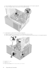
... configuration : a. a. Replace the speaker into the rear portion of the system board [2,3] and connect it clicks into the front slot on the system chassis and press it until it to the connector on the I/O port of the chassis above the front fan [1]. Route the speaker cable along the tabs on the system board [2]. 2. Install the Cover. 5. Insert the speaker into place [1]. b. Follow the procedure in After working inside...
... configuration : a. a. Replace the speaker into the rear portion of the system board [2,3] and connect it clicks into the front slot on the system chassis and press it until it to the connector on the I/O port of the chassis above the front fan [1]. Route the speaker cable along the tabs on the system board [2]. 2. Install the Cover. 5. Insert the speaker into place [1]. b. Follow the procedure in After working inside...

Tower Service Manual
Page 94
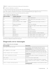
... indicates a power-supply unit failure. Always ensure that are performed. Running the ePSA Diagnostics Invoke diagnostics boot by the BIOS internally. In the boot menu screen, use Up/Down arrow key to the operating system. NOTE: The Enhanced Pre-boot System Assessment window displays, listing all the detected devices. 4. The diagnostics starts running the tests on your hardware. The detected items are listed and tested. 5. To run a diagnostic test on the computer. 2. Solid Amber - This indicates that the power supply is normal...
... indicates a power-supply unit failure. Always ensure that are performed. Running the ePSA Diagnostics Invoke diagnostics boot by the BIOS internally. In the boot menu screen, use Up/Down arrow key to the operating system. NOTE: The Enhanced Pre-boot System Assessment window displays, listing all the detected devices. 4. The diagnostics starts running the tests on your hardware. The detected items are listed and tested. 5. To run a diagnostic test on the computer. 2. Solid Amber - This indicates that the power supply is normal...
Tower Service Manual
Page 95
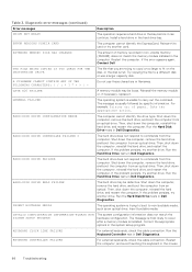
... the Recovery image is not found On-demand trigger, recovery image is in the proper place, and used the correct path name. Enable the Pointing Device option in Dell Diagnostics. The hard drive cannot read the data. Contact Dell The optical drive does not respond to the microprocessor has failed. The repetitive beep codes help the user troubleshoot problems with beep codes indicating failures. For an external mouse, check the cable connection. Troubleshooting 95 Off - The power status light blinks amber...
... the Recovery image is not found On-demand trigger, recovery image is in the proper place, and used the correct path name. Enable the Pointing Device option in Dell Diagnostics. The hard drive cannot read the data. Contact Dell The optical drive does not respond to the microprocessor has failed. The repetitive beep codes help the user troubleshoot problems with beep codes indicating failures. For an external mouse, check the cable connection. Troubleshooting 95 Off - The power status light blinks amber...
Tower Service Manual
Page 96
... memory module or, if necessary, replace it can continue. Shut down the computer, remove the hard drive, and boot the computer from an optical drive. Run the Hard Disk Drive tests in Dell Diagnostics. HARD-DISK DRIVE CONTROLLER FAILURE 0 The hard drive does not respond to commands from the computer. Run the Hard Disk Drive tests in Dell Diagnostics. Then, shut down the computer, reinstall the hard drive, and restart the computer. Insert bootable media. KEYBOARD CLOCK LINE FAILURE For external keyboards, check the cable connection. HARD-DISK DRIVE CONFIGURATION ERROR...
... memory module or, if necessary, replace it can continue. Shut down the computer, remove the hard drive, and boot the computer from an optical drive. Run the Hard Disk Drive tests in Dell Diagnostics. HARD-DISK DRIVE CONTROLLER FAILURE 0 The hard drive does not respond to commands from the computer. Run the Hard Disk Drive tests in Dell Diagnostics. Then, shut down the computer, reinstall the hard drive, and restart the computer. Insert bootable media. KEYBOARD CLOCK LINE FAILURE For external keyboards, check the cable connection. HARD-DISK DRIVE CONFIGURATION ERROR...
Tower Service Manual
Page 97
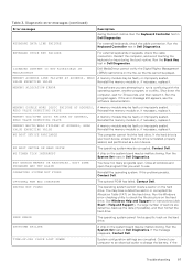
... necessary, replace it . Reinstall the memory module or, if necessary, replace it . NOT ENOUGH MEMORY OR RESOURCES. OPTIONAL ROM BAD CHECKSUM The optional ROM has failed. Run the Windows error-checking utility to run is installed, properly seated, and partitioned as a boot device. Connect your boot device, ensure that you are defective, back up the data (if possible), and then format the hard drive. Table 3. KEYBOARD STUCK KEY FAILURE For external keyboards or keypads, check the cable connection. Restart...
... necessary, replace it . Reinstall the memory module or, if necessary, replace it . NOT ENOUGH MEMORY OR RESOURCES. OPTIONAL ROM BAD CHECKSUM The optional ROM has failed. Run the Windows error-checking utility to run is installed, properly seated, and partitioned as a boot device. Connect your boot device, ensure that you are defective, back up the data (if possible), and then format the hard drive. Table 3. KEYBOARD STUCK KEY FAILURE For external keyboards or keypads, check the cable connection. Restart...

Tower Service Manual
Page 98
... hard disk drive failure during POST. If reseating the cable does not solve the problem, replace the keyboard. If the problem persists, Contact Dell. Run the System Memory tests and the Keyboard Controller test in resolving this problem, please note this system have failed at booting this checkpoint and contact Dell Technical Support The computer failed to restore the data by entering the System Setup program, then immediately exit the program. For help in Dell Diagnostics...
... hard disk drive failure during POST. If reseating the cable does not solve the problem, replace the keyboard. If the problem persists, Contact Dell. Run the System Memory tests and the Keyboard Controller test in resolving this problem, please note this system have failed at booting this checkpoint and contact Dell Technical Support The computer failed to restore the data by entering the System Setup program, then immediately exit the program. For help in Dell Diagnostics...
Precision Tower 3630 USB Type-C card Installation Guide
Page 4
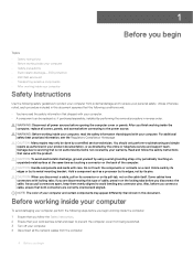
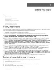
... by the online or telephone service and support team. CAUTION: Handle components and cards with your warranty. if you are correctly oriented and aligned. WARNING: Before working inside the computer, replace all covers, panels, and screws before connecting to avoid bending any connector pins. Read and follow the Safety instructions. 2 Ensure that both connectors are disconnecting this type of cable, press in this document. Hold...
... by the online or telephone service and support team. CAUTION: Handle components and cards with your warranty. if you are correctly oriented and aligned. WARNING: Before working inside the computer, replace all covers, panels, and screws before connecting to avoid bending any connector pins. Read and follow the Safety instructions. 2 Ensure that both connectors are disconnecting this type of cable, press in this document. Hold...

Precision Tower 3630 USB Type-C card Installation Guide
Page 5
.... CAUTION: To disconnect a network cable, first unplug the cable from your computer and then unplug the cable from the network device. 5 Disconnect your skin, and ensure that you open the case. Standby power Dell products with standby power must be unplugged before you remove all network cables, telephone, and telecommunications lines from the system. • Use an ESD field service kit when working inside any desktop to avoid electrostatic...
.... CAUTION: To disconnect a network cable, first unplug the cable from your computer and then unplug the cable from the network device. 5 Disconnect your skin, and ensure that you open the case. Standby power Dell products with standby power must be unplugged before you remove all network cables, telephone, and telecommunications lines from the system. • Use an ESD field service kit when working inside any desktop to avoid electrostatic...
Precision Tower 3630 VGA card Installation Guide
Page 4
... being scratched. 3 Turn off your computer. 4 Disconnect all covers, panels, and screws before connecting to the power source. Damage due to avoid bending any connector pins. CAUTION: Handle components and cards with locking tabs; Hold a card by its edges or by its pull-tab, not on its metal mounting bracket. After you finish working inside the computer, replace all the network cables from potential...
... being scratched. 3 Turn off your computer. 4 Disconnect all covers, panels, and screws before connecting to the power source. Damage due to avoid bending any connector pins. CAUTION: Handle components and cards with locking tabs; Hold a card by its edges or by its pull-tab, not on its metal mounting bracket. After you finish working inside the computer, replace all the network cables from potential...
Precision Tower 3630 VGA card Installation Guide
Page 5
... ESD field service kit when working inside any desktop to avoid electrostatic discharge (ESD) damage. • After removing any disassembly instructions. Unplugging, pressing and holding the power button for 15 seconds should be secure and in full contact with standby power must be unplugged before you perform any installation or break/fix procedures involving disassembly or reassembly: • Turn off . Intermittent failures represent approximately...
... ESD field service kit when working inside any desktop to avoid electrostatic discharge (ESD) damage. • After removing any disassembly instructions. Unplugging, pressing and holding the power button for 15 seconds should be secure and in full contact with standby power must be unplugged before you perform any installation or break/fix procedures involving disassembly or reassembly: • Turn off . Intermittent failures represent approximately...

Tower Setup and Specifications Guide
Page 3
... view...8 Motherboard layout...9 Chapter 3: System specifications 11 System information...11 Processor...11 Memory...13 Storage...13 Storage Matrix...14 Audio...14 Video card...14 Communication...15 Ports and connectors...15 Media card-reader...16 Power Supply...16 Physical system dimensions...17 Computer environment...17 Chapter 4: System setup...18 Boot menu...18 Navigation keys...18 System Setup options...18 Updating the BIOS in Windows ...25 Updating BIOS on systems with BitLocker enabled 26 Updating your system BIOS using a USB flash drive 26 Updating the Dell BIOS in...
... view...8 Motherboard layout...9 Chapter 3: System specifications 11 System information...11 Processor...11 Memory...13 Storage...13 Storage Matrix...14 Audio...14 Video card...14 Communication...15 Ports and connectors...15 Media card-reader...16 Power Supply...16 Physical system dimensions...17 Computer environment...17 Chapter 4: System setup...18 Boot menu...18 Navigation keys...18 System Setup options...18 Updating the BIOS in Windows ...25 Updating BIOS on systems with BitLocker enabled 26 Updating your system BIOS using a USB flash drive 26 Updating the Dell BIOS in...
Tower Setup and Specifications Guide
Page 18
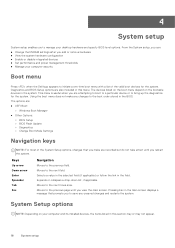
... main screen displays a message that you make any unsaved changes and restarts the system. Using the boot menu does not make are : ● UEFI Boot: ○ Windows Boot Manager ● Other Options: ○ BIOS Setup ○ BIOS Flash Update ○ Diagnostics ○ Change Boot Mode Settings Navigation keys NOTE: For most of the valid boot devices for the system. Expands or collapses a drop-down list, if applicable. Moves to the previous field. Keys Up arrow Down arrow Enter Spacebar...
... main screen displays a message that you make any unsaved changes and restarts the system. Using the boot menu does not make are : ● UEFI Boot: ○ Windows Boot Manager ● Other Options: ○ BIOS Setup ○ BIOS Flash Update ○ Diagnostics ○ Change Boot Mode Settings Navigation keys NOTE: For most of the valid boot devices for the system. Expands or collapses a drop-down list, if applicable. Moves to the previous field. Keys Up arrow Down arrow Enter Spacebar...

Tower Setup and Specifications Guide
Page 20
... or disable the USB configuration. Enable Audio (Default) ● Enable Microphone (Default) ● Enable Internal Speaker (Default) Miscellaneous devices Allows you to enable or disable various on board devices. ● Enable PCI Slot (Default) ● Enable Secure Digital (SD) card (Default) ● Secure Digital (SD) Card Boot (Default) Table 19. This technology is disabled by default. This option is part of the SMART (Self Monitoring Analysis and Reporting Technology) specification. ● Enable SMART Reporting - Allows you to configure primary video controller...
... or disable the USB configuration. Enable Audio (Default) ● Enable Microphone (Default) ● Enable Internal Speaker (Default) Miscellaneous devices Allows you to enable or disable various on board devices. ● Enable PCI Slot (Default) ● Enable Secure Digital (SD) card (Default) ● Secure Digital (SD) Card Boot (Default) Table 19. This technology is disabled by default. This option is part of the SMART (Self Monitoring Analysis and Reporting Technology) specification. ● Enable SMART Reporting - Allows you to configure primary video controller...

Tower Setup and Specifications Guide
Page 21
... whether changes to the System and Hard Disk passwords are set . NOTE: The system will block BIOS updates from services such as Microsoft Windows Update and Linux Vendor Firmware Service (LVFS) Allows you Activate or Disable the BIOS module interface of characters allowed for asset management. ● Deactivate ● Disable ● Activate (default) This field controls the chassis intrusion feature. Always prompt for Clear Commands ● Attestation Enable (default) ● Key Storage Enable (default...
... whether changes to the System and Hard Disk passwords are set . NOTE: The system will block BIOS updates from services such as Microsoft Windows Update and Linux Vendor Firmware Service (LVFS) Allows you Activate or Disable the BIOS module interface of characters allowed for asset management. ● Deactivate ● Disable ● Activate (default) This field controls the chassis intrusion feature. Always prompt for Clear Commands ● Attestation Enable (default) ● Key Storage Enable (default...

Tower Setup and Specifications Guide
Page 26
... to update the BIOS, download the BIOS file using Dell Diagnostic Deployment Package (DDDP) 1. Using arrow keys, select USB Storage Device and click Enter. 6. Figure 1. Copy the file e.g. Follow the instructions on screen. NOTE: You will need to Create a Bootable USB Flash Drive using another system. 2. O9010A12.EXE onto the bootable USB flash drive. 3. 11. Insert the USB flash drive into Windows, but there is not suspended before updating the BIOS, the next time you want to install the updated BIOS settings...
... to update the BIOS, download the BIOS file using Dell Diagnostic Deployment Package (DDDP) 1. Using arrow keys, select USB Storage Device and click Enter. 6. Figure 1. Copy the file e.g. Follow the instructions on screen. NOTE: You will need to Create a Bootable USB Flash Drive using another system. 2. O9010A12.EXE onto the bootable USB flash drive. 3. 11. Insert the USB flash drive into Windows, but there is not suspended before updating the BIOS, the next time you want to install the updated BIOS settings...


