

Precision Tower 3620 Owners Manual
Page 3
... the memory module...13 Installing the PCIe Solid State Drive SSD...14 Removing the PCIe Solid State Drive SSD ...15 Removing the power supply unit PSU...15 Installing the power supply unit PSU...16 Removing the Input-Output panel...16 Installing the Input-Output panel...17 Removing the speaker...17 Installing the speaker...18...
... the memory module...13 Installing the PCIe Solid State Drive SSD...14 Removing the PCIe Solid State Drive SSD ...15 Removing the power supply unit PSU...15 Installing the power supply unit PSU...16 Removing the Input-Output panel...16 Installing the Input-Output panel...17 Removing the speaker...17 Installing the speaker...18...

Precision Tower 3620 Owners Manual
Page 15
... the procedure in Before Working Inside Your Computer. 2 Remove the cover. 3 Press the tab of the 4-pin power cables and disconnect it from the system board [1,2]. 4 Release the cables from the clip [3]. 5 To remove the power supply unit (PSU): a Remove the screws that secures the PCIe SSD card. 2 Slide and lift the PCIe...
... the procedure in Before Working Inside Your Computer. 2 Remove the cover. 3 Press the tab of the 4-pin power cables and disconnect it from the system board [1,2]. 4 Release the cables from the clip [3]. 5 To remove the power supply unit (PSU): a Remove the screws that secures the PCIe SSD card. 2 Slide and lift the PCIe...

Precision Tower 3620 Owners Manual
Page 16
... left of the computer [6]. 16 Removing and installing components b Remove the screw that secures the I/O panel to the connectors on the system board. Installing the power supply unit PSU 1 Insert the PSU into place. 2 Tighten the screws to secure the PSU to the computer. 3 Route the PSU cables through the retention clips...
... left of the computer [6]. 16 Removing and installing components b Remove the screw that secures the I/O panel to the connectors on the system board. Installing the power supply unit PSU 1 Insert the PSU into place. 2 Tighten the screws to secure the PSU to the computer. 3 Route the PSU cables through the retention clips...
Precision Tower 3620 Owners Manual
Page 31
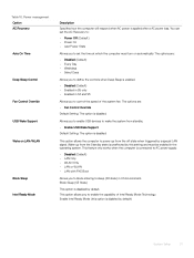
The options are : • Fan Control Override Default Setting: The option is connected to AC power supply. • Disabled (Default) • LAN Only • WLAN Only • LAN or WLAN • LAN with PXE Boot Allows you to enable the capability of ... Control Override USB Wake Support Wake on automatically. The options are : • Disabled (Default) • Every Day • Weekdays • Select Days Allows you to power up from the Standby state is enabled. • Disabled (Default) • Enabled in S5 only • Enabled in S4 and S5 Allows you to define...
The options are : • Fan Control Override Default Setting: The option is connected to AC power supply. • Disabled (Default) • LAN Only • WLAN Only • LAN or WLAN • LAN with PXE Boot Allows you to enable the capability of ... Control Override USB Wake Support Wake on automatically. The options are : • Disabled (Default) • Every Day • Weekdays • Select Days Allows you to power up from the Standby state is enabled. • Disabled (Default) • Enabled in S5 only • Enabled in S4 and S5 Allows you to define...
Precision Tower 3620 Owners Manual
Page 38
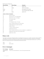
... Amber LED state White LED state off off off blinking blinking off steady off off steady Description system is OFF system is in sleep state power supply unit (PSU) failure PSU is working but failed to fetch code system is ON Amber LED state Description 2,1 system board failure 2,2 system board, PSU or... 3 sec, and the beep sound lasts 300 ms. After each beep and each set of beeps, the BIOS should detect if the user presses the power button.
... Amber LED state White LED state off off off blinking blinking off steady off off steady Description system is OFF system is in sleep state power supply unit (PSU) failure PSU is working but failed to fetch code system is ON Amber LED state Description 2,1 system board failure 2,2 system board, PSU or... 3 sec, and the beep sound lasts 300 ms. After each beep and each set of beeps, the BIOS should detect if the user presses the power button.
Precision Tower 3620 Owners Manual
Page 45
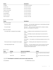
... connector One 2-pin connector One 4-pin connector One 3-pin connector One 8-pin. Green - the computer is functional. The power supply is turned on and is not detecting a physical connection to the power connector (at the back of the computer. Coin cell battery 3 V CR2032 lithium coin cell Voltage 100 V AC to ... the network and the computer. one 4-pin, Table 30. A blinking yellow light indicates that the computer is calculated by using the power supply wattage rating. a 100 Mbps connection exists between the network and the computer. Table 31. Solid white light indicates...
... connector One 2-pin connector One 4-pin connector One 3-pin connector One 8-pin. Green - the computer is functional. The power supply is turned on and is not detecting a physical connection to the power connector (at the back of the computer. Coin cell battery 3 V CR2032 lithium coin cell Voltage 100 V AC to ... the network and the computer. one 4-pin, Table 30. A blinking yellow light indicates that the computer is calculated by using the power supply wattage rating. a 100 Mbps connection exists between the network and the computer. Table 31. Solid white light indicates...


