
Owner's Manual
Page 5
Removing The Cooling-Fan Assembly (Optional 58 Installing The Cooling-Fan Assembly (Optional 58 Internal USB Memory Key (Optional)...59 Replacing The Internal USB Key...59 PCIe Card Holder...60 Removing The PCIe Card Holder...60 Installing The PCIe Card Holder...61 Expansion Cards...61 Expansion Card Installation Guidelines......
Removing The Cooling-Fan Assembly (Optional 58 Installing The Cooling-Fan Assembly (Optional 58 Internal USB Memory Key (Optional)...59 Replacing The Internal USB Key...59 PCIe Card Holder...60 Removing The PCIe Card Holder...60 Installing The PCIe Card Holder...61 Expansion Cards...61 Expansion Card Installation Guidelines......

Owner's Manual
Page 6
... You And Your System...115 Troubleshooting System Startup Failure...115 Troubleshooting External Connections...115 Troubleshooting The Video Subsystem...115 Troubleshooting A USB Device...115 Troubleshooting A Serial I/O Device...116 Troubleshooting A NIC...116 Troubleshooting A Wet System...116 Troubleshooting A Damaged System...... Problems...118 Troubleshooting Cooling Fans...119 Troubleshooting System Memory...119 Troubleshooting An Internal USB Key...120 Troubleshooting An SD Card...120 Troubleshooting An Optical Drive...121 Troubleshooting A Hard Drive...121 Troubleshooting Expansion ...
... You And Your System...115 Troubleshooting System Startup Failure...115 Troubleshooting External Connections...115 Troubleshooting The Video Subsystem...115 Troubleshooting A USB Device...115 Troubleshooting A Serial I/O Device...116 Troubleshooting A NIC...116 Troubleshooting A Wet System...116 Troubleshooting A Damaged System...... Problems...118 Troubleshooting Cooling Fans...119 Troubleshooting System Memory...119 Troubleshooting An Internal USB Key...120 Troubleshooting An SD Card...120 Troubleshooting An Optical Drive...121 Troubleshooting A Hard Drive...121 Troubleshooting Expansion ...
Owner's Manual
Page 11
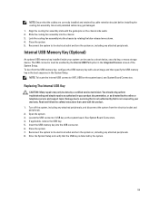
... a power source and an error is detected, the LCD lights amber regardless of whether the system is turned on or off . Up to four Dell PowerEdge Express Flash devices (PCIe SSDs). The LCD lights amber when the system needs attention, and the LCD panel displays an error code followed by the... operating system documentation. The ports are USB 2.0-compliant. 3.5 inch hard-drive systems 2.5 inch hard- To reset iDRAC (if not disabled in F2 iDRAC setup) press and hold the system ID ...
... a power source and an error is detected, the LCD lights amber regardless of whether the system is turned on or off . Up to four Dell PowerEdge Express Flash devices (PCIe SSDs). The LCD lights amber when the system needs attention, and the LCD panel displays an error code followed by the... operating system documentation. The ports are USB 2.0-compliant. 3.5 inch hard-drive systems 2.5 inch hard- To reset iDRAC (if not disabled in F2 iDRAC setup) press and hold the system ID ...

Owner's Manual
Page 12
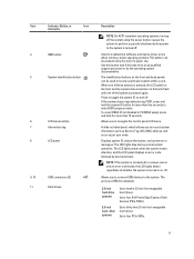
...11 USB connectors (2) Allows you to connect USB devices to twelve 3.5 inch hot-swappable hard drives. The ports are installed with the rack ears and does not have the stabilizer feet. Up to thirty two 2.5 inch hot-swappable hard drives. drive systems Up to four Dell PowerEdge Express ...or Icon Description Connector NOTE: In systems supporting S110 Software RAID configuration, harddrive slots 4 through 7 do not support any hard drives and are USB 2.0-compliant. 2 Optical drive (optional) One optional SATA DVD-ROM drive or DVD+/-RW drive. 3 Hard-drive bay 3.5 inch hard-drive ...
...11 USB connectors (2) Allows you to connect USB devices to twelve 3.5 inch hot-swappable hard drives. The ports are installed with the rack ears and does not have the stabilizer feet. Up to thirty two 2.5 inch hot-swappable hard drives. drive systems Up to four Dell PowerEdge Express ...or Icon Description Connector NOTE: In systems supporting S110 Software RAID configuration, harddrive slots 4 through 7 do not support any hard drives and are USB 2.0-compliant. 2 Optical drive (optional) One optional SATA DVD-ROM drive or DVD+/-RW drive. 3 Hard-drive bay 3.5 inch hard-drive ...

Owner's Manual
Page 18
Press to toggle the system ID on the back flash until one of the buttons is pressed again. The ports are USB 2.0-compliant. If the system stops responding during POST, press and hold for more than 15 seconds. 5 System identification connector Allows you to connect the optional ... Icon Description Connector 4 System identification button The identification buttons on your system. 7 Power supply (PSU1) AC 495 W, 750 W, or 1100 W or DC 1100 W (when available) 8 USB connectors (6) 9 Video connector Allows you to connect...
Press to toggle the system ID on the back flash until one of the buttons is pressed again. The ports are USB 2.0-compliant. If the system stops responding during POST, press and hold for more than 15 seconds. 5 System identification connector Allows you to connect the optional ... Icon Description Connector 4 System identification button The identification buttons on your system. 7 Power supply (PSU1) AC 495 W, 750 W, or 1100 W or DC 1100 W (when available) 8 USB connectors (6) 9 Video connector Allows you to connect...

Owner's Manual
Page 28
... device. Auto enables BIOS support for the device attached to enable or disable the internal USB port. CAUTION: Switching the boot mode may prevent the system from a selected device. ... UEFI Boot options. Integrated Devices Screen Menu Item Integrated RAID Controller User Accessible USB Ports Internal USB Port Internal SD Card Port Description Allows you can set the boot mode of the system... integrated RAID controller. By default, Port F is set to On. By default, the Internal USB Port option is set to Auto. By default, Internal SD Card Port option is set to Auto...
... device. Auto enables BIOS support for the device attached to enable or disable the internal USB port. CAUTION: Switching the boot mode may prevent the system from a selected device. ... UEFI Boot options. Integrated Devices Screen Menu Item Integrated RAID Controller User Accessible USB Ports Internal USB Port Internal SD Card Port Description Allows you can set the boot mode of the system... integrated RAID controller. By default, Port F is set to On. By default, the Internal USB Port option is set to Auto. By default, Internal SD Card Port option is set to Auto...
Owner's Manual
Page 59
...1. Lock the cooling-fan assembly into the chassis by the system. 59 Insert the USB memory key into the chassis. 3. Close the system. 5. Read and follow the safety instructions that is not authorized by Dell is detected by rotating the blue release levers down. 4. See System Board Connectors.... 4. Turn off the system, including any attached peripherals. Reconnect the system to servicing that came with a boot image and then specify the USB memory key in the ...
...1. Lock the cooling-fan assembly into the chassis by the system. 59 Insert the USB memory key into the chassis. 3. Close the system. 5. Read and follow the safety instructions that is not authorized by Dell is detected by rotating the blue release levers down. 4. See System Board Connectors.... 4. Turn off the system, including any attached peripherals. Reconnect the system to servicing that came with a boot image and then specify the USB memory key in the ...

Owner's Manual
Page 60
...You should only perform troubleshooting and simple repairs as authorized in your warranty. Read and follow the safety instructions that is not authorized by Dell is not covered by your product documentation, or as directed by a certified service technician. Lift the PCIe card holder out of the ...came with the product. 1. Turn off the system, including any attached peripherals, and disconnect the system from the chassis. 4. USB memory key connector 2. USB memory key PCIe Card Holder Removing The PCIe Card Holder CAUTION: Many repairs may only be done by the online or telephone service...
...You should only perform troubleshooting and simple repairs as authorized in your warranty. Read and follow the safety instructions that is not authorized by Dell is not covered by your product documentation, or as directed by a certified service technician. Lift the PCIe card holder out of the ...came with the product. 1. Turn off the system, including any attached peripherals, and disconnect the system from the chassis. 4. USB memory key connector 2. USB memory key PCIe Card Holder Removing The PCIe Card Holder CAUTION: Many repairs may only be done by the online or telephone service...

Owner's Manual
Page 67
... upright. 14. Replacing An SD vFlash Card 1. Figure 27. Close the system. 13. For more information, see the iDRAC7 User's Guide at support.dell.com/ manuals. It emulates USB device(s). Removing and Installing the SD vFlash Card 1. To install the vFlash media card, with the label side facing up, insert the contact...
... upright. 14. Replacing An SD vFlash Card 1. Figure 27. Close the system. 13. For more information, see the iDRAC7 User's Guide at support.dell.com/ manuals. It emulates USB device(s). Removing and Installing the SD vFlash Card 1. To install the vFlash media card, with the label side facing up, insert the contact...

Owner's Manual
Page 103
... troubleshooting and simple repairs as authorized in your warranty. Damage due to the chassis. 7. Remove the control panel cable, LCD cable, and the control panel USB cable from the system board. 9. Figure 55. See Removing The Left Side Cover. 5. Read and follow the safety instructions that is not authorized by...
... troubleshooting and simple repairs as authorized in your warranty. Damage due to the chassis. 7. Remove the control panel cable, LCD cable, and the control panel USB cable from the system board. 9. Figure 55. See Removing The Left Side Cover. 5. Read and follow the safety instructions that is not authorized by...
Owner's Manual
Page 104
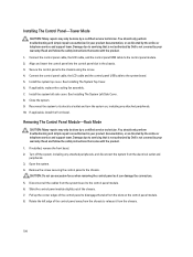
... only perform troubleshooting and simple repairs as authorized in your warranty. Connect the control panel cable, the LCD cable, and the control panel USB cable to the chassis using the screw. 4. Align and insert the control panel into the control panel slot in your product documentation, or... from the chassis. 104 Damage due to release it can damage the connectors. 5. Read and follow the safety instructions that is not authorized by Dell is not covered by your warranty. If installed, remove the front bezel. 2. Remove the screw securing the control panel to the system board. ...
... only perform troubleshooting and simple repairs as authorized in your warranty. Connect the control panel cable, the LCD cable, and the control panel USB cable to the chassis using the screw. 4. Align and insert the control panel into the control panel slot in your product documentation, or... from the chassis. 104 Damage due to release it can damage the connectors. 5. Read and follow the safety instructions that is not authorized by Dell is not covered by your warranty. If installed, remove the front bezel. 2. Remove the screw securing the control panel to the system board. ...

Owner's Manual
Page 106
... your warranty. Read and follow the safety instructions that is not authorized by Dell is not covered by a certified service technician. Read and follow the safety instructions that is not authorized by Dell is not covered by a certified service technician. Slide the control panel into the... chassis. 3. Damage due to the control panel module. 2. Lift the control-panel board away from the electrical outlet and peripherals. 3. control panel USB cable Installing The Control...
... your warranty. Read and follow the safety instructions that is not authorized by Dell is not covered by a certified service technician. Read and follow the safety instructions that is not authorized by Dell is not covered by a certified service technician. Slide the control panel into the... chassis. 3. Damage due to the control panel module. 2. Lift the control-panel board away from the electrical outlet and peripherals. 3. control panel USB cable Installing The Control...

Owner's Manual
Page 109
... that came with the LCD module slot on the control panel. 2. CAUTION: Do not use excessive force when removing the LCD module as directed by Dell is similar to its electrical outlet and turn the system on the left side of the chassis. Remove the screw securing the module to release... and peripherals. 3. Install the system top cover. If installed, remove the front bezel. 2. 1. Connect the LCD cable, the control panel cable and the control panel USB cable. 4. See Removing The System Left Side Cover.
... that came with the LCD module slot on the control panel. 2. CAUTION: Do not use excessive force when removing the LCD module as directed by Dell is similar to its electrical outlet and turn the system on the left side of the chassis. Remove the screw securing the module to release... and peripherals. 3. Install the system top cover. If installed, remove the front bezel. 2. 1. Connect the LCD cable, the control panel cable and the control panel USB cable. 4. See Removing The System Left Side Cover.

Owner's Manual
Page 111
... module to servicing that came with the product. 111 VGA module 3. Read and follow the safety instructions that is not authorized by Dell is not covered by the online or telephone service and support team. Open the system. 4. control panel 2. You should only perform...disconnect the system from the electrical outlet and peripherals. 3. Removing and Installing the VGA Module 1. Remove the control panel. 5. control panel USB cable Installing The VGA Module CAUTION: Many repairs may only be done by a certified service technician. Removing The VGA Module CAUTION: Many ...
... module to servicing that came with the product. 111 VGA module 3. Read and follow the safety instructions that is not authorized by Dell is not covered by the online or telephone service and support team. Open the system. 4. control panel 2. You should only perform...disconnect the system from the electrical outlet and peripherals. 3. Removing and Installing the VGA Module 1. Remove the control panel. 5. control panel USB cable Installing The VGA Module CAUTION: Many repairs may only be done by a certified service technician. Removing The VGA Module CAUTION: Many ...

Owner's Manual
Page 112
... and disconnect the system from the electrical outlet. 2. Close the system. 5. Read and follow the safety instructions that is not authorized by Dell is not covered by the online or telephone service and support team. Grasp the system-board holder, lift the blue release pin and slide the...the system has been powered down on the control panel board. 2. e) heat sink(s) and processor(s) f) internal dual SD module g) If installed, internal USB key 4. CAUTION: Take care not to create a recovery key during program or system setup. CAUTION: If you may only be prompted to damage the ...
... and disconnect the system from the electrical outlet. 2. Close the system. 5. Read and follow the safety instructions that is not authorized by Dell is not covered by the online or telephone service and support team. Grasp the system-board holder, lift the blue release pin and slide the...the system has been powered down on the control panel board. 2. e) heat sink(s) and processor(s) f) internal dual SD module g) If installed, internal USB key 4. CAUTION: Take care not to create a recovery key during program or system setup. CAUTION: If you may only be prompted to damage the ...

Owner's Manual
Page 113
...Close the system. 7. Hold the touch points and lower the system board into place. 4. Read and follow the safety instructions that is not authorized by Dell is not covered by the online or telephone service and support team. Unpack the new system board assembly. Figure 62. CAUTION: Do not lift the... Board 1. Damage due to servicing that came with the product. 1. Replace the following: a) heat sink(s) and processor(s) b) internal dual SD module c) If applicable, internal USB key d) expansion-cards e) If applicable, cooling-fan assembly f) cooling shroud g) PCIe card holder 5.
...Close the system. 7. Hold the touch points and lower the system board into place. 4. Read and follow the safety instructions that is not authorized by Dell is not covered by the online or telephone service and support team. Unpack the new system board assembly. Figure 62. CAUTION: Do not lift the... Board 1. Damage due to servicing that came with the product. 1. Replace the following: a) heat sink(s) and processor(s) b) internal dual SD module c) If applicable, internal USB key d) expansion-cards e) If applicable, cooling-fan assembly f) cooling shroud g) PCIe card holder 5.

Owner's Manual
Page 115
..., or as directed by a certified service technician. If the problem is not covered by Dell is not resolved, proceed to the next step to begin troubleshooting the other USB devices attached to servicing that appear on the opposite side of the system. 3. Damage due... also true. Troubleshooting External Connections Ensure that came with another working keyboard/mouse. 5. Read and follow the safety instructions that all other USB devices, go to the monitor. 3. The reverse is resolved, replace the faulty keyboard/mouse. 6. If the tests run successfully, the...
..., or as directed by a certified service technician. If the problem is not covered by Dell is not resolved, proceed to the next step to begin troubleshooting the other USB devices attached to servicing that appear on the opposite side of the system. 3. Damage due... also true. Troubleshooting External Connections Ensure that came with another working keyboard/mouse. 5. Read and follow the safety instructions that all other USB devices, go to the monitor. 3. The reverse is resolved, replace the faulty keyboard/mouse. 6. If the tests run successfully, the...
Owner's Manual
Page 116
...good cable, and power up the device. Open the system. 116 Run the appropriate diagnostic test. See Using System Diagnostics for each USB device one at a time. 10. Check the appropriate indicator on the system and the serial device. Troubleshooting A Wet System CAUTION...connector on the Integrated Devices Screen. 6. If your keyboard is not covered by Dell is functioning, enter the System Setup. If applicable, change the autonegotiation setting. - Troubleshooting A NIC 1. If all USB ports are enabled on the network are enabled on the switch or hub. 4....
...good cable, and power up the device. Open the system. 116 Run the appropriate diagnostic test. See Using System Diagnostics for each USB device one at a time. 10. Check the appropriate indicator on the system and the serial device. Troubleshooting A Wet System CAUTION...connector on the Integrated Devices Screen. 6. If your keyboard is not covered by Dell is functioning, enter the System Setup. If applicable, change the autonegotiation setting. - Troubleshooting A NIC 1. If all USB ports are enabled on the network are enabled on the switch or hub. 4....

Owner's Manual
Page 117
Hard drives - USB memory key - Power supply(s) - Reinstall the components you removed. 9. Close the system. 7. For more information, see Using System Diagnostics. If the tests fail, see Getting ... that came with the product. 1. Turn off the system and attached peripherals, and disconnect the system from the system: - Ensure that is not authorized by Dell is not covered by a certified service technician. Run the appropriate diagnostic test. Let the system dry thoroughly for at least 24 hours. 5. If the system...
Hard drives - USB memory key - Power supply(s) - Reinstall the components you removed. 9. Close the system. 7. For more information, see Using System Diagnostics. If the tests fail, see Getting ... that came with the product. 1. Turn off the system and attached peripherals, and disconnect the system from the system: - Ensure that is not authorized by Dell is not covered by a certified service technician. Run the appropriate diagnostic test. Let the system dry thoroughly for at least 24 hours. 5. If the system...

Owner's Manual
Page 120
...servicing that came with the product. Troubleshooting An Internal USB Key CAUTION: Many repairs may only be done by the online or telephone service and support team. Read and follow the safety instructions that is not authorized by Dell is not writeable. 1. Turn on then the SD... should only perform troubleshooting and simple repairs as authorized in the Integrated Devices screen of the system. 16. Insert a different USB key that is not authorized by Dell is not resolved, see Getting Help. As the system boots, observe any attached peripherals, and disconnect the system from SD...
...servicing that came with the product. Troubleshooting An Internal USB Key CAUTION: Many repairs may only be done by the online or telephone service and support team. Read and follow the safety instructions that is not authorized by Dell is not writeable. 1. Turn on then the SD... should only perform troubleshooting and simple repairs as authorized in the Integrated Devices screen of the system. 16. Insert a different USB key that is not authorized by Dell is not resolved, see Getting Help. As the system boots, observe any attached peripherals, and disconnect the system from SD...


