Owner's Manual
Page 13
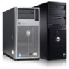
...Your System 13 See "Using the System Setup Program and Boot Manager" on the system. • If necessary to the system and external devices before attaching a new external device. The ports are USB 2.0-compliant. Connects additional storage devices. Turn on any external...attached device has been installed on page 23. Item Indicator, Button, or Icon Connector 5 USB connectors (4) 6 eSATA connector 7 Serial connector 8 Video connector 9 Ethernet connector Description Connect USB devices to four PCI Express expansion cards. Integrated 10/100/1000 NIC connector. 10 PCIe ...
...Your System 13 See "Using the System Setup Program and Boot Manager" on the system. • If necessary to the system and external devices before attaching a new external device. The ports are USB 2.0-compliant. Connects additional storage devices. Turn on any external...attached device has been installed on page 23. Item Indicator, Button, or Icon Connector 5 USB connectors (4) 6 eSATA connector 7 Serial connector 8 Video connector 9 Ethernet connector Description Connect USB devices to four PCI Express expansion cards. Integrated 10/100/1000 NIC connector. 10 PCIe ...
Owner's Manual
Page 18
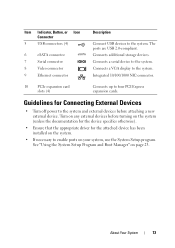
... optical drive subsystem, hard drive, or hard-drive subsystem, or no bootable USB key installed. Use a bootable USB key, CD, or hard drive. See "Using the System Setup Program and Boot Manager" on page 23 for information on page 100. "Troubleshooting a USB Device" on setting the order of manufacturing mode. The system will run...
... optical drive subsystem, hard drive, or hard-drive subsystem, or no bootable USB key installed. Use a bootable USB key, CD, or hard drive. See "Using the System Setup Program and Boot Manager" on page 23 for information on page 100. "Troubleshooting a USB Device" on setting the order of manufacturing mode. The system will run...
Owner's Manual
Page 29
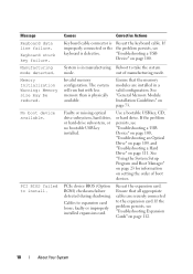
If the operating system supports Unified Extensible Firmware Interface (UEFI), you can set this field to UEFI disables the Boot Sequence, Hard-Disk Drive Sequence, and USB Flash Drive Emulation Type fields. Setting this field to BIOS allows compatibility with non-UEFI operating systems. NOTE: Setting this... or disables the user-accessible USB ports. Auto enables BIOS support for the device. If this field is enabled and the system has failed to boot, the system re-attempts to SATA port C. Off disables BIOS support for the device attached to boot after 30 seconds. Option Port...
If the operating system supports Unified Extensible Firmware Interface (UEFI), you can set this field to UEFI disables the Boot Sequence, Hard-Disk Drive Sequence, and USB Flash Drive Emulation Type fields. Setting this field to BIOS allows compatibility with non-UEFI operating systems. NOTE: Setting this... or disables the user-accessible USB ports. Auto enables BIOS support for the device. If this field is enabled and the system has failed to boot, the system re-attempts to SATA port C. Off disables BIOS support for the device attached to boot after 30 seconds. Option Port...
Owner's Manual
Page 36
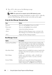
... wish to access the System Setup program, System Services (Dell Unified Server Configurator [USC]), Diagnostics, and BIOS-level boot options. 36 Using the System Setup Program and Boot Manager change boot order; Displays the list of available boot options (marked with asterisks). Enables you to use and ...before you press , allow the system to devices starting with the first item in the boot order until the USB keyboard is successful or no more boot options are found. Refreshes the Boot Manager screen, or returns to and highlights the previous field. 2 Press after you see...
... wish to access the System Setup program, System Services (Dell Unified Server Configurator [USC]), Diagnostics, and BIOS-level boot options. 36 Using the System Setup Program and Boot Manager change boot order; Displays the list of available boot options (marked with asterisks). Enables you to use and ...before you press , allow the system to devices starting with the first item in the boot order until the USB keyboard is successful or no more boot options are found. Refreshes the Boot Manager screen, or returns to and highlights the previous field. 2 Press after you see...

Owner's Manual
Page 88
...product. 1 Turn off the system, including any attached peripherals, and disconnect the system from the USB memory key, configure the USB memory key with a boot image and then specify the USB memory key in the boot sequence in the Integrated Devices screen of the power supply. 6 Connect all the power cables ..."Closing the System" on the side of the System Setup program. Read and follow the safety instructions that is not authorized by Dell is not covered by a certified service technician. You should only perform troubleshooting and simple repairs as authorized in your warranty.
...product. 1 Turn off the system, including any attached peripherals, and disconnect the system from the USB memory key, configure the USB memory key with a boot image and then specify the USB memory key in the boot sequence in the Integrated Devices screen of the power supply. 6 Connect all the power cables ..."Closing the System" on the side of the System Setup program. Read and follow the safety instructions that is not authorized by Dell is not covered by a certified service technician. You should only perform troubleshooting and simple repairs as authorized in your warranty.

Owner's Manual
Page 108
..., proceed with the product. 1 Enter the System Setup program and ensure that is not authorized by Dell is still indicated, repeat step 12 through step 15 for each memory module installed. Troubleshooting an Internal USB Key CAUTION: Many repairs may only be done by the online or telephone service and support team...page 46. 10 Enter the System Setup program and check the system memory setting. See "Closing the System" on page 46. 15 As the system boots, observe any error message that came with the next step. 11 Open the system. See "Opening the System" on the front of the same type...
..., proceed with the product. 1 Enter the System Setup program and ensure that is not authorized by Dell is still indicated, repeat step 12 through step 15 for each memory module installed. Troubleshooting an Internal USB Key CAUTION: Many repairs may only be done by the online or telephone service and support team...page 46. 10 Enter the System Setup program and check the system memory setting. See "Closing the System" on page 46. 15 As the system boots, observe any error message that came with the next step. 11 Open the system. See "Opening the System" on the front of the same type...

Owner's Manual
Page 109
... controller. 8 Ensure that a power cable is properly connected to servicing that is not authorized by Dell is not resolved, see "Getting Help" on page 123. Read and follow the safety instructions that... from the electrical outlet. 5 Open the system. See "Using the System Setup Program and Boot Manager" on page 23. 3 Run the appropriate online diagnostic test. If the problem is not resolved, repeat ...step 2 and step 3. 8 Insert a different USB key that the integrated SATA controller and the drive's SATA port are enabled. Damage due to the...
... controller. 8 Ensure that a power cable is properly connected to servicing that is not authorized by Dell is not resolved, see "Getting Help" on page 123. Read and follow the safety instructions that... from the electrical outlet. 5 Open the system. See "Using the System Setup Program and Boot Manager" on page 23. 3 Run the appropriate online diagnostic test. If the problem is not resolved, repeat ...step 2 and step 3. 8 Insert a different USB key that the integrated SATA controller and the drive's SATA port are enabled. Damage due to the...
Owner's Manual
Page 129
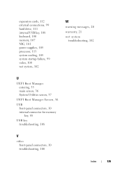
expansion cards, 112 external connections, 99 hard drive, 111 internal USB key, 108 keyboard, 100 memory, 107 NIC, 101 power supplies, 105 processor, 113 system cooling, 105 system startup failure, 99 video, 100 wet system, 102 W warning messages, 20 warranty, 21 wet system troubleshooting, 102 U UEFI Boot Manager entering, 35 main screen, 36 System Utilities screen, 37 UEFI Boot Manager Screen, 36 USB front-panel connectors, 10 internal connector for memory key, 88 USB key troubleshooting, 108 V video front-panel connectors, 10 troubleshooting, 100 Index 129
expansion cards, 112 external connections, 99 hard drive, 111 internal USB key, 108 keyboard, 100 memory, 107 NIC, 101 power supplies, 105 processor, 113 system cooling, 105 system startup failure, 99 video, 100 wet system, 102 W warning messages, 20 warranty, 21 wet system troubleshooting, 102 U UEFI Boot Manager entering, 35 main screen, 36 System Utilities screen, 37 UEFI Boot Manager Screen, 36 USB front-panel connectors, 10 internal connector for memory key, 88 USB key troubleshooting, 108 V video front-panel connectors, 10 troubleshooting, 100 Index 129
Technical Guide
Page 37
For more information on the PowerEdge T110 II: No optical drive configuration DVD-ROM (SATA) DVD+RW (SATA) 12.6 Tape Drives Internal and external tape drives and tape libraries are supported. PowerEdge T110 II Technical Guide 37 The following internal optical drives configurations are available on supported tape drives and tape libraries, see Dell.com/Storage. 12.5 Optical Drives The PowerEdge T110 II supports two internal optical drives and an optional external USB DVD-ROM. The T110 II is able to boot from any internal optical drive.
For more information on the PowerEdge T110 II: No optical drive configuration DVD-ROM (SATA) DVD+RW (SATA) 12.6 Tape Drives Internal and external tape drives and tape libraries are supported. PowerEdge T110 II Technical Guide 37 The following internal optical drives configurations are available on supported tape drives and tape libraries, see Dell.com/Storage. 12.5 Optical Drives The PowerEdge T110 II supports two internal optical drives and an optional external USB DVD-ROM. The T110 II is able to boot from any internal optical drive.


