
Getting Started Guide
Page 10
... 8 GB 1 GB 32 GB Up to four 3.5-inch, cabled SAS or SATA internal drives Optional internal SATA DVD-ROM or SATA DVD+/-RW Optional external USB DVD-ROM NOTE: DVD devices are data only. One optional internal half-height tape backup device 8 Getting Started With Your System
... 8 GB 1 GB 32 GB Up to four 3.5-inch, cabled SAS or SATA internal drives Optional internal SATA DVD-ROM or SATA DVD+/-RW Optional external USB DVD-ROM NOTE: DVD devices are data only. One optional internal half-height tape backup device 8 Getting Started With Your System

Getting Started Guide
Page 11
... coin cell Getting Started With Your System 9 Connectors Back NIC Serial USB Video eSATA Front USB Internal USB One RJ-45 (for integrated 1 GB NIC) 9-pin, DTE, 16550-compatible Four 4-pin, USB 2.0-compliant 15-pin VGA One 7-pin connector Two 4-pin, USB 2.0-compliant Two 4-pin, USB 2.0-compliant Video Video type Video memory Matrox G200, integrated in...
... coin cell Getting Started With Your System 9 Connectors Back NIC Serial USB Video eSATA Front USB Internal USB One RJ-45 (for integrated 1 GB NIC) 9-pin, DTE, 16550-compatible Four 4-pin, USB 2.0-compliant 15-pin VGA One 7-pin connector Two 4-pin, USB 2.0-compliant Two 4-pin, USB 2.0-compliant Video Video type Video memory Matrox G200, integrated in...

Owner's Manual
Page 6
... Cooling Fan 83 System Battery 84 Replacing the System Battery 84 Power Supply 86 Removing the Power Supply 86 Installing the Power Supply 87 Internal USB Memory Key 88 Chassis Intrusion Switch 89 Removing the Chassis Intrusion Switch 89 Installing the Chassis Intrusion Switch 90 Control Panel Assembly 91 Removing the...
... Cooling Fan 83 System Battery 84 Replacing the System Battery 84 Power Supply 86 Removing the Power Supply 86 Installing the Power Supply 87 Internal USB Memory Key 88 Chassis Intrusion Switch 89 Removing the Chassis Intrusion Switch 89 Installing the Chassis Intrusion Switch 90 Control Panel Assembly 91 Removing the...

Owner's Manual
Page 7
...Safety First-For You and Your System 99 Troubleshooting System Startup Failure 99 Troubleshooting External Connections 99 Troubleshooting the Video Subsystem 100 Troubleshooting a USB Device 100 Troubleshooting a Serial I/O Device 101 Troubleshooting a NIC 101 Troubleshooting a Wet System 102 Troubleshooting a Damaged System 103 Troubleshooting ...Troubleshooting System Cooling Problems 105 Troubleshooting Cooling Fan 106 Troubleshooting System Memory 107 Troubleshooting an Internal USB Key 108 Troubleshooting an Optical Drive 109 Troubleshooting a Tape Backup Unit 110 Contents 7
...Safety First-For You and Your System 99 Troubleshooting System Startup Failure 99 Troubleshooting External Connections 99 Troubleshooting the Video Subsystem 100 Troubleshooting a USB Device 100 Troubleshooting a Serial I/O Device 101 Troubleshooting a NIC 101 Troubleshooting a Wet System 102 Troubleshooting a Damaged System 103 Troubleshooting ...Troubleshooting System Cooling Problems 105 Troubleshooting Cooling Fan 106 Troubleshooting System Memory 107 Troubleshooting an Internal USB Key 108 Troubleshooting an Optical Drive 109 Troubleshooting a Tape Backup Unit 110 Contents 7

Owner's Manual
Page 11
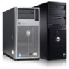
... indicator lights display error codes during system startup. Item Indicator, Button, or Icon Connector 2 System health indicator 3 Hard-drive activity indicator 4 USB connectors (2) 5 Diagnostic indicator lights (4) 6 Tape drive (optional) 7 Optical drive (optional) Description The system health indicator blinks amber when a... Your System 11 The ports are data only. NOTE: DVD devices are USB 2.0-compliant. The hard drive activity indicator lights up when the hard drive is detected. Connect USB devices to the system. One optional SATA DVD-ROM drive or DVD+/-RW...
... indicator lights display error codes during system startup. Item Indicator, Button, or Icon Connector 2 System health indicator 3 Hard-drive activity indicator 4 USB connectors (2) 5 Diagnostic indicator lights (4) 6 Tape drive (optional) 7 Optical drive (optional) Description The system health indicator blinks amber when a... Your System 11 The ports are data only. NOTE: DVD devices are USB 2.0-compliant. The hard drive activity indicator lights up when the hard drive is detected. Connect USB devices to the system. One optional SATA DVD-ROM drive or DVD+/-RW...
Owner's Manual
Page 13
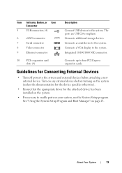
... been installed on the system. • If necessary to the system. The ports are USB 2.0-compliant. Connects additional storage devices. Item Indicator, Button, or Icon Connector 5 USB connectors (4) 6 eSATA connector 7 Serial connector 8 Video connector 9 Ethernet connector Description Connect USB devices to enable ports on your system, use the System Setup program. About Your...
... been installed on the system. • If necessary to the system. The ports are USB 2.0-compliant. Connects additional storage devices. Item Indicator, Button, or Icon Connector 5 USB connectors (4) 6 eSATA connector 7 Serial connector 8 Video connector 9 Ethernet connector Description Connect USB devices to enable ports on your system, use the System Setup program. About Your...

Owner's Manual
Page 16
... and/or system board hardware failure. See "Getting Help" on page 107. Ensure that the hard drives are properly connected. Possible USB failure. Memory configuration See "Troubleshooting System error. Other failure. Memory" on page 123. Possible system resource configuration error. If the ...problem persists, see "Getting Help" on page 100. Code Causes Hard drive failure. See "Troubleshooting a USB Device" on page 123. 16 About Your System See "Getting Help" on page 99 for information on the drives installed in your ...
... and/or system board hardware failure. See "Getting Help" on page 107. Ensure that the hard drives are properly connected. Possible USB failure. Memory configuration See "Troubleshooting System error. Other failure. Memory" on page 123. Possible system resource configuration error. If the ...problem persists, see "Getting Help" on page 100. Code Causes Hard drive failure. See "Troubleshooting a USB Device" on page 123. 16 About Your System See "Getting Help" on page 99 for information on the drives installed in your ...
Owner's Manual
Page 18
... is physically available. Invalid memory configuration. Cables to install. See "General Memory Module Installation Guidelines" on page 100. Use a bootable USB key, CD, or hard drive. Reseat the expansion card. If improperly connected or the the problem persists, see "Troubleshooting Expansion Cards" on... is defective. PCIe device BIOS (Option ROM) checksum failure detected during shadowing. No boot device available. "Troubleshooting a USB Device" on page 73. Ensure that all appropriate cables are installed in manufacturing mode. If the problem persists, see "Troubleshooting...
... is physically available. Invalid memory configuration. Cables to install. See "General Memory Module Installation Guidelines" on page 100. Use a bootable USB key, CD, or hard drive. Reseat the expansion card. If improperly connected or the the problem persists, see "Troubleshooting Expansion Cards" on... is defective. PCIe device BIOS (Option ROM) checksum failure detected during shadowing. No boot device available. "Troubleshooting a USB Device" on page 73. Ensure that all appropriate cables are installed in manufacturing mode. If the problem persists, see "Troubleshooting...
Owner's Manual
Page 29
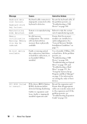
... Unified Extensible Firmware Interface (UEFI), you can set this field to UEFI disables the Boot Sequence, Hard-Disk Drive Sequence, and USB Flash Drive Emulation Type fields. Setting this field to BIOS allows compatibility with non-UEFI operating systems. NOTE: Setting this option to...Off. Auto enables BIOS support for the device. Integrated Devices Screen Option User Accessible USB Ports (All Ports On default) Internal USB Port (On default) Description Enables or disables the user-accessible USB ports. Off disables BIOS support for the device attached to SATA port D. Enables...
... Unified Extensible Firmware Interface (UEFI), you can set this field to UEFI disables the Boot Sequence, Hard-Disk Drive Sequence, and USB Flash Drive Emulation Type fields. Setting this field to BIOS allows compatibility with non-UEFI operating systems. NOTE: Setting this option to...Off. Auto enables BIOS support for the device. Integrated Devices Screen Option User Accessible USB Ports (All Ports On default) Internal USB Port (On default) Description Enables or disables the user-accessible USB ports. Off disables BIOS support for the device attached to SATA port D. Enables...
Owner's Manual
Page 36
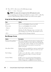
Refreshes the Boot Manager screen, or returns to access the System Setup program, System Services (Dell Unified Server Configurator [USC]), Diagnostics, and BIOS-level boot options. 36 Using the System Setup Program and Boot Manager If the boot attempt fails, the ... to boot to use and press Enter. Displays the list of available boot options (marked with the first item in the boot order until the USB keyboard is successful or no more boot options are found. or execute a one-time boot option. Using the Boot Manager Navigation Keys Keys Up arrow...
Refreshes the Boot Manager screen, or returns to access the System Setup program, System Services (Dell Unified Server Configurator [USC]), Diagnostics, and BIOS-level boot options. 36 Using the System Setup Program and Boot Manager If the boot attempt fails, the ... to boot to use and press Enter. Displays the list of available boot options (marked with the first item in the boot order until the USB keyboard is successful or no more boot options are found. or execute a one-time boot option. Using the Boot Manager Navigation Keys Keys Up arrow...

Owner's Manual
Page 88
...Secure the I/O panel and SATA cables (if present) to the routing clip on page 67. 8 Replace the expansion-card stabilizer. Internal USB Memory Key An optional USB memory key installed inside your system can be done by a certified service technician. Read and follow the safety instructions that came with a boot..."Using the System Setup Program and Boot Manager" on page 46. 6 Enter the System Setup program and verify that is not authorized by Dell is not covered by the online or telephone service and support team. See "Integrated Devices Screen" on the system board. Damage due to ...
...Secure the I/O panel and SATA cables (if present) to the routing clip on page 67. 8 Replace the expansion-card stabilizer. Internal USB Memory Key An optional USB memory key installed inside your system can be done by a certified service technician. Read and follow the safety instructions that came with a boot..."Using the System Setup Program and Boot Manager" on page 46. 6 Enter the System Setup program and verify that is not authorized by Dell is not covered by the online or telephone service and support team. See "Integrated Devices Screen" on the system board. Damage due to ...

Owner's Manual
Page 89
Read and follow the safety instructions that is not authorized by Dell is not covered by the online or telephone service and support team. You should only perform troubleshooting and simple repairs as authorized in your ...the product. 1 Turn off the system and attached peripherals, and disconnect the system from the INTRUSION connector on the system board. Removing and Installing a USB Memory Key 1 2 1 USB memory key 2 USB memory key connector Chassis Intrusion Switch Removing the Chassis Intrusion Switch CAUTION: Many repairs may only be done by a certified service technician.
Read and follow the safety instructions that is not authorized by Dell is not covered by the online or telephone service and support team. You should only perform troubleshooting and simple repairs as authorized in your ...the product. 1 Turn off the system and attached peripherals, and disconnect the system from the INTRUSION connector on the system board. Removing and Installing a USB Memory Key 1 2 1 USB memory key 2 USB memory key connector Chassis Intrusion Switch Removing the Chassis Intrusion Switch CAUTION: Many repairs may only be done by a certified service technician.

Owner's Manual
Page 100
...resolved, replace the faulty keyboard/mouse. 6 If the problem is resolved, restart the system, enter the System Setup program, and check if the nonfunctioning USB ports are enabled. If the system is not accessible, see "Getting Help" on the opposite side of the system. 3 If the problem is ...not resolved, proceed to the next step to begin troubleshooting the other USB devices attached to the monitor. 3 Run the appropriate online diagnostic test. If the tests run successfully, the problem is not functioning, you can ...
...resolved, replace the faulty keyboard/mouse. 6 If the problem is resolved, restart the system, enter the System Setup program, and check if the nonfunctioning USB ports are enabled. If the system is not accessible, see "Getting Help" on the opposite side of the system. 3 If the problem is ...not resolved, proceed to the next step to begin troubleshooting the other USB devices attached to the monitor. 3 Run the appropriate online diagnostic test. If the tests run successfully, the problem is not functioning, you can ...

Owner's Manual
Page 101
... on page 14. See "NIC Indicator Codes" on the switch or hub. 10 If a device causes the same problem, power down the device, replace the USB cable, and power up the device. If the problem persists, replace the device.
... on page 14. See "NIC Indicator Codes" on the switch or hub. 10 If a device causes the same problem, power down the device, replace the USB cable, and power up the device. If the problem persists, replace the device.

Owner's Manual
Page 102
... See "Integrated Devices Screen" on page 29. 6 Ensure that the NICs, hubs, and switches on page 43. • Hard drives • USB memory key • Cooling shroud and expansion-card stabilizer • Expansion cards • Power supply • Cooling fan • Processor and heat ...sink • Memory modules 4 Let the system dry thoroughly for each network device. 7 Ensure that is not authorized by Dell is not covered by your product documentation, or as directed by a certified service technician. Troubleshooting a Wet System CAUTION: Many repairs may only ...
... See "Integrated Devices Screen" on page 29. 6 Ensure that the NICs, hubs, and switches on page 43. • Hard drives • USB memory key • Cooling shroud and expansion-card stabilizer • Expansion cards • Power supply • Cooling fan • Processor and heat ...sink • Memory modules 4 Let the system dry thoroughly for each network device. 7 Ensure that is not authorized by Dell is not covered by your product documentation, or as directed by a certified service technician. Troubleshooting a Wet System CAUTION: Many repairs may only ...

Owner's Manual
Page 108
...problem is not resolved, proceed with the product. 1 Enter the System Setup program and ensure that is not authorized by Dell is enabled. See "Integrated Devices Screen" on page 45. 4 Locate the USB key and reseat it. 5 Close the system. See "Opening the System" on page 29. 2 Turn off the ...test or error message indicates a specific memory module as directed by the online or telephone service and support team. Damage due to servicing that the USB key port is not covered by a certified service technician. See "Opening the System" on page 123. Read and follow the safety instructions that...
...problem is not resolved, proceed with the product. 1 Enter the System Setup program and ensure that is not authorized by Dell is enabled. See "Integrated Devices Screen" on page 45. 4 Locate the USB key and reseat it. 5 Close the system. See "Opening the System" on page 29. 2 Turn off the ...test or error message indicates a specific memory module as directed by the online or telephone service and support team. Damage due to servicing that the USB key port is not covered by a certified service technician. See "Opening the System" on page 123. Read and follow the safety instructions that...

Owner's Manual
Page 109
...If the problem is not resolved, see "Getting Help" on page 123. Damage due to servicing that a power cable is not covered by Dell is properly connected to the controller. 8 Ensure that is not authorized by your product documentation, or as directed by a certified service technician. See...Troubleshooting Your System 109 See "Opening the System" on page 46. If the problem is not resolved, repeat step 2 and step 3. 8 Insert a different USB key that the integrated SATA controller and the drive's SATA port are enabled. See "Closing the System" on page 46. 6 Turn on the system and...
...If the problem is not resolved, see "Getting Help" on page 123. Damage due to servicing that a power cable is not covered by Dell is properly connected to the controller. 8 Ensure that is not authorized by your product documentation, or as directed by a certified service technician. See...Troubleshooting Your System 109 See "Opening the System" on page 46. If the problem is not resolved, repeat step 2 and step 3. 8 Insert a different USB key that the integrated SATA controller and the drive's SATA port are enabled. See "Closing the System" on page 46. 6 Turn on the system and...

Owner's Manual
Page 117
... left side of the Customize window lists devices that can select: • Non-Interactive Tests Only-Runs only tests that you want to specify the USB memory key where the test log file is run. • Log output file pathname-Enables you to run on any component to test, highlight All...
... left side of the Customize window lists devices that can select: • Non-Interactive Tests Only-Runs only tests that you want to specify the USB memory key where the test log file is run. • Log output file pathname-Enables you to run on any component to test, highlight All...

Owner's Manual
Page 121
... fan connector PCIe x8 half length PCIe x8 full length PCIe x4 half length Battery socket PCIe x1 half length Auxiliary hard-drive LED Internal USB key 1 and 2 Processor DIMM_A2 memory module slot DIMM_A1 memory module slot Power connector 12 V DIMM_B1 memory module slot DIMM_B2 memory module slot Control panel connector...
... fan connector PCIe x8 half length PCIe x8 full length PCIe x4 half length Battery socket PCIe x1 half length Auxiliary hard-drive LED Internal USB key 1 and 2 Processor DIMM_A2 memory module slot DIMM_A1 memory module slot Power connector 12 V DIMM_B1 memory module slot DIMM_B2 memory module slot Control panel connector...

Owner's Manual
Page 125
..., 52 chassis intrusion switch installing, 90 removing, 89 replacing, 90 closing the system, 46 connectors USB, 10, 12 video, 10, 12 contacting Dell, 123 cooling fan installing, 83 removing, 82 replacing, 83 troubleshooting, 106 D damaged systems troubleshooting, 103 Dell contacting, 123 Dell PowerEdge Diagnostics using, 115 diagnostics advanced testing options, 117 testing options, 116 using...
..., 52 chassis intrusion switch installing, 90 removing, 89 replacing, 90 closing the system, 46 connectors USB, 10, 12 video, 10, 12 contacting Dell, 123 cooling fan installing, 83 removing, 82 replacing, 83 troubleshooting, 106 D damaged systems troubleshooting, 103 Dell contacting, 123 Dell PowerEdge Diagnostics using, 115 diagnostics advanced testing options, 117 testing options, 116 using...


